
4 Absorption and Stripping
Overview of Absorption and Stripping Processes
 = fraction not absorbed (unitless)
 = fraction not stripped (unitless)
 = absorption factor (unitless)
 = equilibrium constant, (mole fraction in gas)/(mole fraction in liquid)
 = total liquid flow rate (mol time-1)
 = total gas flow rate (mol time-1)
 = stripping factor (unitless)
 (lowercase) = mol fraction of solute in liquid phase (mol solute/mol total liquid)
 (uppercase) = mol ratio of solute in liquid phase (mol solute/mol solvent)
 (lowercase) = mol fraction of solute in gas phase (mol solute/mol total vapor)
 (uppercase) = mol ratio of solute in gas phase (mol solute/mol gaseous carrier)
(8.1) 
(8.2) 
Example
K for acetone in an air/water system is 2.0. We intend to absorb 90% of the acetone entering in the gaseous phase into the liquid phase. How many theoretical stages would be required for (L/V) = 1, (L/V) = 2, and (L/V) = 10?
Finding mole ratio from mole fraction:
(8.3) 
(8.4) 
Finding mole fraction from mole ratio:
(8.5) 
(8.6) 
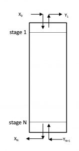
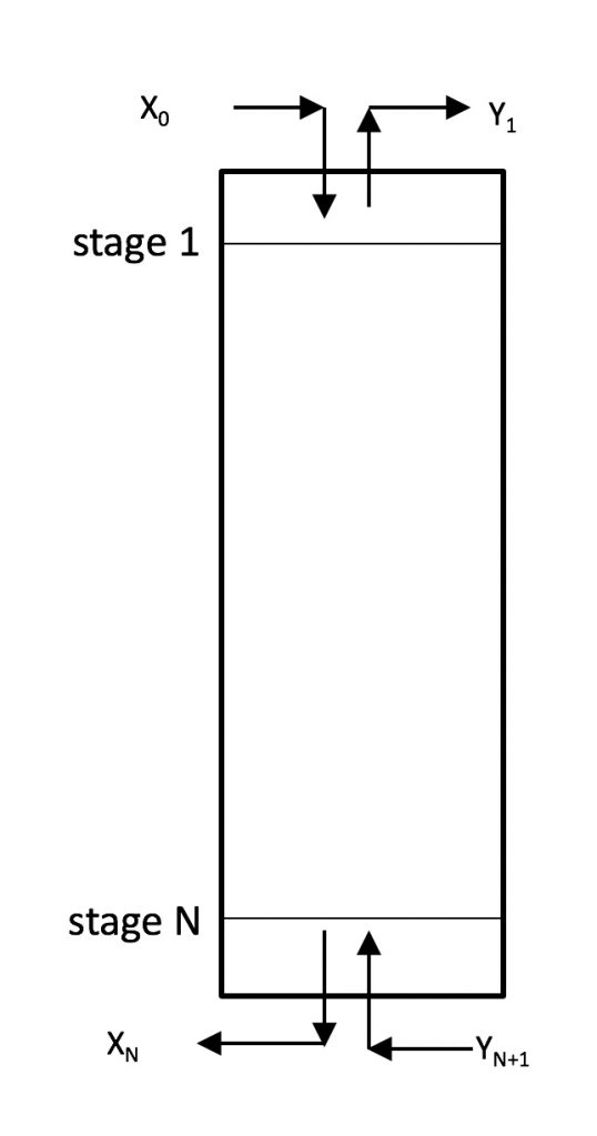
Graphical Method to Find Equilibrium Stages for Absorption Columns
= equilibrium constant, (mole fraction in gas)/(mole fraction in liquid)
= liquid flow rate (mol time-1)
 = liquid flow rate on a solute-free basis (mol time-1)
 = total number of stages. For an absorption column, is the bottom stage. For a stripping column, is the top stage.
 = generic stage number
= gas flow rate (mol total time-1)
 = gas flow rate on a solute-free basis (mol gaseous carrier time-1)
= mole fraction of solute in liquid phase (mol solute/mol total liquid)
= mole ratio of solute in liquid phase (mol solute/mol liquid absorbent)
 = mole ratio of solute/absorbent in liquid entering the top of the absorption column
 = mole ratio of solute/absorbent in liquid leaving the bottom of the absorption column
= mole fraction of solute in gas phase (mol solute/mol total gas)
= mole ratio of solute in gas phase (mol solute/mol gaseous carrier)
 = mole ratio of solute/gaseous carrier in gas leaving the top of the absorption column
 = mole ratio of solute/gaseous carrier in gas entering the bottom of the absorption column
Operating line for absorption column:
(9.1) 
Watch a video from LearnChemE that demonstrates how to determine the number of equilibrium stages required for an absorption column when given inlet and outlet specifications: Absorption of a Dilute Species (10:43): https://youtu.be/BoPKngZZwVI
Example
The following equilibrium data is available for water, ammonia, and air at 20°C.

We intend to use fresh water to absorb the ammonia from a stream of air containing 28.5 mol% ammonia, with both streams at 20°C. We intend to absorb 80% of the incoming ammonia. How many equilibrium stages are required for each of the following design cases?
(a)  = 1.0
= 1.0
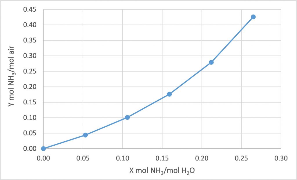
(b) = 1.6

(c) = 2.0
Determining the Minimum Ratio for Absorbent to Gas Flow Rates and a Mathematical Approach for Finding the Number of Equilibrium Stages
= equilibrium constant, (mole fraction solute in gas)/(mole fraction solute in liquid)
 = liquid flow rate on a solute-free basis (mol liquid absorbent time-1)
= generic equilibrium stage
= bottom equilibrium stage for an absorption column
= gas flow rate on a solute-free basis (mol gaseous carrier time-1)
 = relative molar flowrates of solute-free absorbent and solute-free carrier gas at which an infinite number of equilibrium stages is required in order to achieve the desired separation
= mole fraction of solute in liquid phase (mol solute/mol total liquid)
= mole ratio of solute in liquid phase (mol solute/mol liquid absorbent)
= mole ratio of solute/absorbent in liquid entering the top of the absorption column
= mole ratio of solute/absorbent in liquid leaving the bottom of the absorption column
= mole fraction of solute in gas phase (mol solute/mol total gas)
= mole ratio of solute in gas phase (mol solute/mol gaseous carrier)
= mole ratio of solute/gaseous carrier in gas leaving the top of the absorption column
= mole ratio of solute/gaseous carrier in gas entering the bottom of the absorption column
Equilibrium:
(10.1) 
Operating line:
(10.2) 
when ~ and ~ ,
(10.3) 
when ~ , ~ and 0 = 0
(10.4) 
Example
180 kmol/hr of off-gas from a fermentation unit contains 98 mol% CO2 and 2 mol% ethanol. We would like to recover 97% of this ethanol and have proposed the use of a staged absorption column with water as the absorbent. The incoming water contains no ethanol and is at 30°C. The incoming gaseous stream is at 30°C, 110 kPa. Assume there is no absorption of CO2 into the water. The activity coefficient at infinite dilution for ethanol in water at 30°C is 6.0 and Psat is 10.5 kPa. Thus, K = γiPisat/P = 0.57.
(a) What is ?
(b) How many equilibrium stages are required if we operate at 1.5*?
Stage Efficiency and Column Height
 = inverse absorption factor (unitless)
 = liquid-phase viscosity (mass time-1 length-1)
 = liquid-phase density (mass volume-1)
 = vapor-liquid interfacial area per volume of combined gas/liquid on the tray (area volume-1)=(length-1)
 = portion of the column cross-sectional area dedicated to mixing of the gas/liquid (area)
 = column diameter (length)
 = Murphree efficiency, calculated on the basis of the vapor phase composition
 = overall stage efficiency
= equilibrium constant (gas-phase composition/liquid-phase composition)
 = overall gas mass-transfer coefficient, partial pressure driving force (mol time-1 area-1 pressure-1)
= molar flow rate of liquid phase (mol time-1)
 = molecular weight of the liquid phase
 = actual number of stages required to achieve the desired separation
 = number of overall gas phase mass transfer units
 = number of theoretical stages required to achieve the desired separation
 = pressure (force area-1)
 = temperature (temperature)
= molar flow rate of gaseous phase (mol time-1)
 = the actual mole fraction of species i in the liquid leaving stage n and entering stage n+1
 = the mole fraction of species i in a gas at some fixed point in the column
 = the actual mole fraction of species i in the gas leaving stage n+1 and entering stage n
 = the actual mole fraction of species i in the gas leaving stage n and entering stage n-1
 = the mole fraction of species i in the gas leaving stage n if it had reached equilibrium with the liquid leaving that stage, where the liquid phase composition is
 = height of combined gas and liquid holdup on the tray (length)
(11.1) 
(11.2) 
0.2 < < 1.6 cP, must be in cP
(11.3) ![\begin{equation*} \log_{10}{E_O}=1.597-0.199\log_{10}{\left(\frac{KM_L{\mu}_L}{{\rho}_L}\right)}-0.0896\left[\log_{10}{\left(\frac{KM_L{\mu}_L}{{\rho}_L}}\right)\right]^{2} \end{equation*}](https://iastate.pressbooks.pub/app/uploads/quicklatex/quicklatex.com-abf7c629a4313257174478c9e7db85e0_l3.png "Rendered by QuickLaTeX.com")
Eq 11.3 is applicable for this range of conditions: must be in cP, must be in lb ft-3; restricted to = 2 in – 9 ft, average = 14.7 – 485 psi, average = 60 – 138°F, = 0.65% – 69%
Example
For our CO2/ethanol/water system, we found that for 97% removal of the ethanol using water as the absorbent and operating at 30°C, 110 kPa, with = 0.57 and  = = 0.828, 7 theoretical stages required. How many actual stages are needed, according to equations 11.2 and 11.3?
- = 0.89 cP
- = 18 lb/lb-mole
- = 62.5 lb ft-3
(11.4) ![\begin{equation*} E_O=\frac{\log_{10}{[1+E_{MV}({\lambda}-1)]}}{\log_{10}{\lambda}} \end{equation*}](https://iastate.pressbooks.pub/app/uploads/quicklatex/quicklatex.com-845e9b6acf21c35c353689dd153039be_l3.png "Rendered by QuickLaTeX.com")
(11.5) 
(11.6) 
(11.7) 
Staged Column Height and Diameter
= liquid-phase density (mass volume-1)
 = vapor-phase density (mass volume-1)
 = liquid-phase surface tension (force length-1)
= total column cross-sectional area (area)
 = active tray area (non downcomer) (area)
 = area of the tray open to vapor (area)
 = column cross-sectional area dedicated to downcomers (area)
= column diameter (length)
 = fraction of flooding operation; usually we use 0.80
 = internal variable, relating the kinetic energy of the liquid and gas streams (unitless)
= molar flowrate of the liquid stream (mol time-1)
 = molecular weight of the gaseous stream
= molecular weight of the liquid stream
 = Vapor velocity that is sufficient to suspend liquid droplets. Vapor velocity greater than can be associated with entrainment flooding (length time-1)
= molar flowrate of the gaseous stream (mol time-1)
*Note that many of the parameters can have different values for different stages in the column. Use an appropriate average value and document and justify your assumptions.
(12.1) ![\begin{equation*} D_T=\left[\frac{4VM_V}{fU_f{\pi}(1-A_d/A){\rho}_V}\right]^{0.5} \end{equation*}](https://iastate.pressbooks.pub/app/uploads/quicklatex/quicklatex.com-47245d41104d25a673cf7952bcb09e36_l3.png "Rendered by QuickLaTeX.com")
(12.2) 
Where  is estimated as follows
if  ,
,
(12.3) 
if  ,
,
(12.4) 
if  ,
,
(12.5) 
Example
180 kmol/hr of fermentation off-gas containing 98 mol% CO2 and 2 mol% ethanol is to be fed to a staged absorption tower that operates at 30°C, 110 kPa. Fresh water will be supplied to this column at a ratio of  = 154 kmol/hr and we intend to have a sufficient number of stages so that 97% of the ethanol will be recovered. Ignore the contribution of the solute to the physical properties of the carrier streams and assume a vapor flooding velocity of 3.12 m/s.
Graphical and Mathematical Determination of Vapor Phase Flooding Velocity
= liquid-phase density (mass volume-1)
= vapor-phase density (mass volume-1)
= liquid surface tension (dyne cm-1)
= active tray area for contact between the gas and liquid phases (area)
= area of the holes (area)
 = Souders and Brown capacity parameter, also known as vapor velocity factor (ft/s)
 = internal parameter for calculation of
  (m s-1)
 = internal parameter for calculation of (m s-1)
 = liquid droplet drag coefficient
 = entrainment flooding capacity, from Figure 6.23 (ft/s)
= ultimate capacity parameter (m s-1)
 = liquid droplet diameter (length)
 = foaming factor (unitless)
 = internal variable based on plate-specific value of Ah/Aa (unitless)
= internal variable, relating the kinetic energy of the liquid and gas streams (unitless)
 = surface tension factor (unitless)
 = internal parameter for calculation of
 = gravitational constant (length time-2)
 = superficial liquid velocity (length time-1)
= superficial vapor velocity at flooding (length time-1)
 = superficial vapor velocity (length time-1)
 = superficial vapor velocity at which the vapor velocity exceeds the liquid droplet settling velocity (m s-1)
Graphical Determination of Superficial Vapor Velocity at Flooding
(13.1) 
(13.2) 
we will use
(13.3) 
(13.4) 
must be in dyne/cm
if  FHA = 1.0
(13.5) 
if  FHA = 5(Ah/Aa) + 0.5
(13.6) 
is from Fig 6.23, needs and tray spacing
Mathematical Determination of Superficial Vapor Velocity at Flooding
(13.7) 
 , whichever value is smaller
(13.8) ![\begin{equation*} C_1=0.445(1-F)\left[\frac{\sigma}{\rho_L-\rho_V}\right]^{0.25}-1.4L_S \end{equation*}](https://iastate.pressbooks.pub/app/uploads/quicklatex/quicklatex.com-5157ef243ce29a2cfdb71dfe3087e64b_l3.png "Rendered by QuickLaTeX.com")
(13.9) ![\begin{equation*} C_2=0.356(1-F)\left[\frac{\sigma}{\rho_L-\rho_V}\right]^{0.25} \end{equation*}](https://iastate.pressbooks.pub/app/uploads/quicklatex/quicklatex.com-46c4ddec1fa193fb63b674bb4931c75d_l3.png "Rendered by QuickLaTeX.com")
(13.10) ![\begin{equation*} F=\left({1+1.4\left[\frac{\rho_L-\rho_V}{\rho_V}\right]^{0.5}\right)^{-1} \end{equation*}](https://iastate.pressbooks.pub/app/uploads/quicklatex/quicklatex.com-d8bfa74f189ed140f3afc73a2c4b8143_l3.png "Rendered by QuickLaTeX.com")
for equations 13.8, 13.9, and 13.10, densities must be in kg/m3 and surface tension must be in dyne/cm
(13.11) 
*true in all conditions, not just flooding
Example
180 kmol/hr of fermentation off-gas containing 98 mol% CO2 and 2 mol% ethanol is to be fed to a staged absorption tower that operates at 30°C, 110 kPa. Fresh water will be supplied to this column at a ratio of = 154 kmol/hr and we intend to have a sufficient number of stages so that 97% of the ethanol will be recovered. Assume a foaming factor of 0.90, trays that have an  and a surface tension of 70 dyne/cm and ignore the contribution of the solute to the physical properties of the carrier streams. Assume a tray spacing of 24 inches. What is according to
(a) the graphical method
(b) ultimate superficial velocity computational method?
Staged Column Pressure Drop
 = height of clear liquid/height of froth (unitless)
= liquid-phase density (mass volume-1)
= vapor-phase density (mass volume-1)
= liquid surface tension (dyne cm-1)
= active tray area, hosting interaction between the gas and liquid phases (area)
= downcomer area, hosting liquid handling (area)
= total area of the holes on each tray (area)
 = tray-specific parameter, generally between 0.68 and 0.85
 = internal parameter in calculation of h
 = maximum bubble size (length). We will use maximum hole diameter
  .
.
= column diameter (length)
= gravitational constant (length time-2)
 = pressure drop due to movement of the gas through tray perforations (inches of our liquid)
 = pressure drop due to movement of the gas through the liquid hold-up (inches of our liquid)
 = pressure drop due to movement of the gas through the liquid surface (inches of our liquid)
 = total pressure drop for a single actual tray (inches of our liquid)
 = weir height (inches)
 = capacity parameter (ft s-1)
 = weir length (inches)
 = liquid flow rate across the tray (gal min-1)
 = velocity of the vapor phase through the holes in the tray (ft s-1)
 = superficial vapor velocity, calculated based on the active bubbling area (ft s-1)
(14.1) 
(14.2) 
(14.3) ![\begin{equation*} h_{l}=\phi_e\left[h_w+C_{l}\left(\frac{q_L}{L_w\phi_e}\right)^{2/3}\right] \end{equation*}](https://iastate.pressbooks.pub/app/uploads/quicklatex/quicklatex.com-06a3e7d6342524455aa8caddf3826477_l3.png "Rendered by QuickLaTeX.com")
(14.4) 
(14.5) 
(14.6) 
(14.7) 
(14.8) 
, must be in inches, must be in gal/min, must be ft/s
(14.9) 
To prevent weeping, maintain
(14.10) 
Example
180 kmol/hr of CO2 containing 2 mol% ethanol and 154 kmol/hr of fresh water are fed to a column with a diameter of 0.80m. The weirs have a height of 2.0 inches, the sieve tray holes have a diameter of 3/16″, C0 = 0.73. Ten percent (10%) of the column cross-sectional area is occupied by the downcomers and 10% of the active column area is occupied by the sieve tray holes. What is the pressure drop per tray?
Staged Column Mass Transfer
= height of clear liquid/height of froth (unitless); equation 14.4 from Lecture 2.2 Staged Column Pressure Drop
= density of the liquid phase (mass volume-1)
= density of the vapor phase (mass volume-1)
= interfacial gas-liquid area per unit volume of combined gas and liquid hold up (area/volume = length-1)
 = interfacial gas-liquid area per unit volume of equivalent clear liquid (area/volume = length-1)
= active tray area, hosting interaction between the gas and liquid phases (area)
= active bubbling area of the tray (area)
 = diffusivity of the solute in the liquid phase (cm2 s-1)
 = diffusivity of the solute in the vapor phase (cm2 s-1)
= Murphree efficiency of a stage, based on the vapor phase
= fractional value representing proximity to flooding value, based on instead of (unitless)
= -factor [(kg/m)0.5s-1]
= pressure drop due to movement of the gas through the liquid hold-up, from Lecture 2.2 Staged Column Pressure Drop (pressure)
 = gas-phase mass transfer coefficient (length time-1)
 = liquid-phase mass transfer coefficient (length time-1)
= equilibrium constant for our system (y/x)
= overall mass transfer coefficient, based on partial-pressure driving force (time-1)
= molar flow rate of the liquid phase (mol time-1)
= molecular weight of the liquid phase (mass mole-1)
 = number of transfer units in the gas phase
 = number of transfer units in the liquid phase
= number of overall mass transfer units, expressed on a gas-phase basis
= pressure of the gas phase (pressure)
= liquid volumetric flow rate across the tray (volume time-1)
 = average gas residence time in the froth (time)
 = average liquid residence time in the froth (time)
= superficial vapor velocity, calculated based on the active bubbling area (length time-1)
= superficial vapor velocity at flooding, found by Souders and Brown or superficial velocity method, Lecture 2.1 Graphical and mathematical determination of vapor phase flooding velocity (length time-1)
= molar flow rate of the gas phase (mole time-1)
= composition (mole fraction) of the gas entering stage n from stage 
= composition (mole fraction) of the gas leaving stage
= composition (mole fraction) of the gas leaving stage n if it had reached equilibrium with the liquid leaving stage
= height of combined gas and liquid hold up (length)
Refer to Lecture 1.13 Stage Efficiency and Column Height for the first part of this topic
(15.1) 
(15.2) 
(15.3) 
(15.4) 
(15.5) 
(15.6) 
(15.7) 
(15.8) 
(15.9) 
(15.10) 
(15.11) 
(15.12) 
(15.13) 
In equations 15.12 and 15.13, and must be in cm2/s, must be in cm, must be in (kg/m)0.5s-1
Example
180 kmol/hr of CO2 containing 2 mol% ethanol is fed to an absorption column. 154 kmol/hr of fresh water is used as the liquid absorbent. The column has a diameter of 0.80m, weir height of 2.0 inches, 3/16” hole diameter, = 0.73, 10% of the column area is occupied by downcomers, 10% of the active area is occupied by sieve tray holes. Based on mass transfer principles, what is the expected Murphree efficiency of each stage? Ignore the contribution of the solute.
At the proposed operating conditions, the diffusivity of ethanol in CO2 is 7.85×10⁻² cm2 s-1 and the diffusivity of ethanol in liquid water is 1.81×10⁻⁵ cm2 s-1
Packed Columns
 = packing void fraction (volume volume-1), tabulated value
= density of the vapor phase (mass volume-1)
= density of the liquid phase (mass volume-1)
= absorption factor (unitless)
= specific surface area of the selected packing (area volume-1), tabulated value
 = specific hydraulic area of the selected packing (area volume-1)
 = dimensionless holdup parameter, tabulated value
= packed bed diameter (length)
= target value of fraction of flooding; for packed columns we typically use 0.5 – 0.7
 = volume of liquid per unit volume of packed bed (volume volume-1)
 = overall height of a gas transfer unit (length) – will be discussed in Lecture 2.7 Packed Bed HOG
= equilibrium constant for our system at our operating condition
 = overall mass transfer coefficient in gas-phase mole fraction units (mole time-1 volume-1)
= liquid phase molar flow rate (mole time-1)
 = depth of packed bed (length)
= vapor phase molecular weight
 = Froude number for the liquid phase, inertial force/gravitational force (unitless)
= number of overall gas-phase mass transfer units
 = Reynolds number for the liquid phase, inertial force/viscous force (unitless)
= cross-sectional area of the packed bed (area)
 = liquid-phase superficial velocity through the packed bed (length time-1)
 = superficial gas velocity at flooding (length time-1)
= vapor phase molar flow rate (mole time-1)
 = mole fraction of the solute in the entering liquid
 = mole fraction of the solute in the entering vapor
 = mole fraction of the solute in the exiting vapor
Packed Bed Diameter Sizing
(16.1) 
Depth of Packing Required
(16.2) 
(16.3) 
(16.4) ![\begin{displaymath} N_{OG}=\left(\frac{A}{A-1}\right) \ln{\left[\left(\frac{A-1}{A}\right)\left(\frac{y_{in}-Kx_{in}}{y_{out}-Kx_{in}}+\frac{1}{A}\right)\right]} \end{displaymath}](https://iastate.pressbooks.pub/app/uploads/quicklatex/quicklatex.com-a14a0d3d58312a813eaf9fbd560cb6c7_l3.png "Rendered by QuickLaTeX.com")
(16.5) 
Example
180 kmol/hr of a fermentation off-gas stream (98 mol% CO2, 2 mol% ethanol) is fed to a packed absorption column. We aim to recover 97% of the incoming ethanol using 154 kmol/hr of fresh water. If HOG = 2.0 ft, what is the required depth of packed bed? K = 0.57.
Liquid Hold-up in a Packed Bed, Operating in Pre-loading Region
(16.6) 
(16.7) 
(16.8) 
if 
(16.9) 
if 
(16.10) 
Example
For our CO2/water/ethanol system, we have proposed to use 50-mm metal Hiflow rings as our packing material and a column diameter that results in a superficial liquid velocity of 0.01 m/s. Find the specific liquid holdup and specific volume available for the gas for this proposed design. Ignore the contribution of the solute.
Parameters for 50mm Hiflow Metal Rings: = 92.3 m2/m3, = 0.876, = 0.977 m3/m3
- = 180 kmol/hr
- = 154 kmol/hr
- = 1000 kg/m3
- = 8.9×10⁻⁴ kg s-1 m-1
Packed Bed Pressure Drop by the Graphical Method
= packing void fraction (volume volume-1), tabulated value
= viscosity of the liquid phase (mass time-1 length-1)
 = density of liquid water (mass volume-1)
 = density of the liquid phase (mass volume-1)
 = density of the vapor phase (mass volume-1)
= internal variable (unitless)
 = packing factor (area volume-1), tabulated value
= liquid phase flow rate (mole time-1)
= liquid phase molecular weight
= vapor phase molecular weight
= liquid-phase superficial velocity through the packed bed (length time-1)
 = superficial gas velocity (length time-1)
= superficial gas velocity at flooding (length time-1)
= vapor phase molar flow rate (mole time-1)
= internal variable for the GPDC method, y-axis value of Figure 6-35 (unitless)
Generalized Pressure Drop Correlation (GPDC) for Finding Flooding Velocity
(17.1) 
(17.2) ![\begin{displaymath} Y=\left(\frac{u_V^2F_P}{g}\right)\left(\frac{\rho_V}{\rho_{H_2O,L}}\right)f[\rho_V]f[\mu_L] \end{displaymath}](https://iastate.pressbooks.pub/app/uploads/quicklatex/quicklatex.com-645830a60324c5f99911e845a9fa6f24_l3.png "Rendered by QuickLaTeX.com")
Example
180 kmol/hr of CO2 containing 2.0 mol% ethanol is fed to a packed column operating at 30°C and 110 kPa. 97% of the ethanol is to be removed via the addition of 154 kmol/hr of fresh water. The packed column contains 1” ceramic Raschig rings.
Find:
(a) the superficial gas velocity associated with flooding
(b) the necessary column diameter if we operate at 70% of flooding
(c) the pressure drop per foot of packing. Ignore the contribution of the solute to the magnitude and physical properties of each phase.
For 1” ceramic Raschig rings:  = 179 ft2/ft3
Packed Bed Pressure Drop by the Mathematical Method
= packing void fraction (volume volume-1), tabulated value
 = actual pressure drop across a packed bed during operation at your condition (pressure)
 = pressure drop across your packed bed during dry operation (pressure)
 = internal parameter for pressure drop calculation at the loading point (unitless)
= viscosity of the liquid (mass time-1 length-1)
 = viscosity of the vapor phase (mass time-1 length-1)
= density of the liquid phase (mass volume-1)
= density of the vapor phase (mass volume-1)
 = resistance coefficient of dry packing (unitless)
 = internal parameter for pressure drop calculation at the loading point (unitless)
= specific surface area of the selected packing (area volume-1), tabulated value
= internal parameter for pressure drop calculation at the loading point (unitless)
 = packing parameter, tabulated value
 = packing parameter (unitless)
 = effective packing diameter (length)
= packed bed diameter (length)
= gravitational constant (length time-2)
= liquid hold-up (volume volume-1)
 = wall factor (unitless)
= liquid phase molar flow rate (mole time-1)
= depth of packed bed (length)
= vapor phase molecular weight
= liquid phase molecular weight
= Froude number, inertial force/gravitational force (unitless)
 = Reynold’s number of the vapor phase, inertial force/viscous force (unitless)
 = internal parameter for pressure drop calculation at the loading point (unitless)
= liquid phase superficial velocity (length time-1)
 = liquid phase superficial velocity at the loading point (length time-1)
= vapor phase superficial velocity (length time-1)
= vapor phase superficial velocity at the flooding point (length time-1)
 = vapor phase superficial velocity at the loading point (length time-1)
= vapor phase molar flow rate (mole time-1)
(18.1) 
(18.2) 
(18.3) 
(18.4) 
(18.5) 
(18.6) 
(18.7) 
*at any operating condition: 
Vapor flooding velocity
(18.8) 
At the loading point:
(18.9) ![\begin{equation*} u_{V,l}=\left(\frac{g}{\Psi_l}\right)^{1/2}\left[\frac{\epsilon}{a^{1/6}}-a^{0.5}{\xi}_{l}^{1/3}\right]{\xi}_{l}^{1/6}\left(\frac{\rho_L}{\rho_V}\right)^{1/2} \end{equation*}](https://iastate.pressbooks.pub/app/uploads/quicklatex/quicklatex.com-a669da0e7aa7c3764c82157d49abfda0_l3.png "Rendered by QuickLaTeX.com")
(18.10) ![\begin{equation*} \Psi_{l}=\frac{g}{C^2}\left[F_{LV}\left(\frac{\mu_L}{\mu_V}\right)^{0.4}\right]^{-2n_s} \end{equation*}](https://iastate.pressbooks.pub/app/uploads/quicklatex/quicklatex.com-701113a4a3d13afca267e3a7ad80673c_l3.png "Rendered by QuickLaTeX.com")
(18.11) 
If  , liquid is disperse,
  ,
, 
If  , liquid is continuous,
  ,
, 
(18.12) 
Example
180 kmol/hr of CO2 containing 2.0 mol% ethanol and 154 kmol/hr fresh liquid water are fed to a packed column containing 1” ceramic Raschig rings. Find (a) superficial gas velocity at flooding; (b) column diameter, if we intend to operate at 70% of the flooding velocity; (c) pressure drop per foot of packing at loading point.
Determining the Overall Height of a Gas-liquid Transfer Unit for a Packed Column
= packing void fraction (volume volume-1), tabulated value
= viscosity of the vapor phase (mass time-1 length-1)
= density of the liquid phase (mass volume-1)
= density of the vapor phase (mass volume-1)
= surface tension of the liquid phase (force length-1)
= specific surface area of the selected packing (area volume-1), tabulated value
 = specific area of the gas/liquid interface (area volume-1)
 = packing parameter, tabulated value
 = packing parameter, tabulated value
 = diffusivity of the solute in the gas phase (length2 time-1)
 = packing hydraulic diameter (length)
= diffusivity of the solute in the liquid phase (length2 time-1)
= gravitational constant (length time-2)
 = height of gas-phase transfer unit, with partial pressure driving force (length)
= liquid hold-up (volume volume-1)
 = height of liquid-phase transfer unit, with mole fraction driving force (length)
= overall height of gas/liquid transfer unit, on a gas phase basis (length)
= equilibrium constant for our species in our selected operating condition
= liquid phase molar flow rate (mole time-1)
 = Froude number of the liquid phase with the hydraulic diameter as the characteristic length (unitless)
 = Reynold’s number of the liquid phase, hydraulic diameter as the characteristic length (unitless)
 = Reynold’s number of the vapor phase, inertial force/viscous force (unitless)
 = Schmidt number of the vapor phase (unitless)
 = Weber number of the liquid phase with the hydraulic diameter as the characteristic length (unitless)
= liquid phase superficial velocity (length time-1)
= vapor phase superficial velocity (length time-1)
= vapor phase molar flow rate (mole time-1)
(19.1) 
(19.2) 
(19.3) 
(19.4) 
(19.5) 
(19.6) 
(19.7) 
(19.8) 
(19.9) 
(19.10) ![\begin{equation*} H_L=\frac{1}{C_L}\left(\frac{1}{12}\right)^{1/6}\left[\frac{4h_L\epsilon}{D_Lau_L}\right]^{0.5}\left(\frac{u_L}{a}\right)\left(\frac{a}{a_{Ph}}\right) \end{equation*}](https://iastate.pressbooks.pub/app/uploads/quicklatex/quicklatex.com-cd19576f9b73063cdd0d60ef1037f9bf_l3.png "Rendered by QuickLaTeX.com")
Example
180 kmol/hr of CO2 containing 2.0 mol% ethanol and 154 kmol/hr liquid water are fed to a packed column with diameter of 1.1m containing 1” (25mm) ceramic Raschig rings, with a pressure drop of 1.1 kPa/m. Find the necessary column height and total pressure drop if we aim to recover 97% of the incoming solute and the column is operated at the loading point. Ignore the contribution of the solute.
Packing properties: =190 m2/m3, =0.680, = 0.577,  = 1.329, = 1.361, = 0.412,
  = 2.454
- Diffusivity of ethanol in CO2 at 30°C = 7.85×10⁻² cm2/s
- Diffusivity of ethanol in water at 30°C = 1.81×10⁻⁵ cm2/s
- = 1000 kg/m3
- = 1.92 kg/m3
 = 70 dyne/cm
- = 8.9×10⁻⁴ kg m-1s-1
- = 1.53×10⁻⁵ kg m-1s-1
