
2 BASIC CONCEPTS AND RELATIONSHIPS
2.1 Static Electricity
It was discovered centuries ago that certain types of materials would mysteriously attract one another after being rubbed together. For example, after rubbing a piece of silk against a piece of glass, the silk and glass would tend to stick together. Indeed, there was an attractive force that could be demonstrated even when the two materials were separated:

Glass and silk aren’t the only materials known to behave like this. Anyone who has ever brushed up against a latex balloon only to find that it tries to stick to them has experienced this same phenomenon. Paraffin wax and wool cloth are another pair of materials early experimenters recognized as manifesting attractive forces after being rubbed together:

This phenomenon became even more interesting when it was discovered that identical materials, after having been rubbed with their respective cloths, always repelled each other:

It was also noted that when a piece of glass rubbed with silk was exposed to a piece of wax rubbed with wool, the two materials would attract one another:

Furthermore, it was found that any material demonstrating properties of attraction or repulsion after being rubbed could be classed into one of two distinct categories: attracted to glass and repelled by wax, or repelled by glass and attracted to wax. It was either one or the other: there were no materials found that would be attracted to or repelled by both glass and wax, or that reacted to one without reacting to the other.
More attention was directed toward the pieces of cloth used to do the rubbing. It was discovered that after rubbing two pieces of glass with two pieces of silk cloth, not only did the glass pieces repel each other but so did the cloths. The same phenomenon held for the pieces of wool used to rub the wax:

Now, this was really strange to witness. After all, none of these objects were visibly altered by the rubbing, yet they definitely behaved differently than before they were rubbed. Whatever change took place to make these materials attract or repel one another was invisible.
Some experimenters speculated that invisible “fluids” were being transferred from one object to another during the process of rubbing and that these “fluids” were able to effect a physical force over a distance. Charles Dufay was one of the early experimenters who demonstrated that there were definitely two different types of changes wrought by rubbing certain pairs of objects together. The fact that there was more than one type of change manifested in these materials was evident by the fact that there were two types of forces produced: attraction and repulsion. The hypothetical fluid transfer became known as a charge.
One pioneering researcher, Benjamin Franklin, came to the conclusion that there was only one fluid exchanged between rubbed objects, and that the two different “charges” were nothing more than either an excess or a deficiency of that one fluid. After experimenting with wax and wool, Franklin suggested that the coarse wool removed some of this invisible fluid from the smooth wax, causing an excess of fluid on the wool and a deficiency of fluid on the wax. The resulting disparity in fluid content between the wool and wax would then cause an attractive force, as the fluid tried to regain its former balance between the two materials.
Postulating the existence of a single “fluid” that was either gained or lost through rubbing accounted best for the observed behavior: that all these materials fell neatly into one of two categories when rubbed, and most importantly, that the two active materials rubbed against each other always fell into opposing categories as evidenced by their invariable attraction to one another. In other words, there was never a time where two materials rubbed against each other both became either positive or negative.
Following Franklin’s speculation of the wool rubbing something off of the wax, the type of charge that was associated with rubbed wax became known as “negative” (because it was supposed to have a deficiency of fluid) while the type of charge associated with the rubbing wool became known as “positive” (because it was supposed to have an excess of fluid). Little did he know that his innocent conjecture would cause much confusion for students of electricity in the future!
Precise measurements of electrical charges were carried out by the French physicist Charles Coulomb in the 1780s using a device called a torsional balance measuring the force generated between two electrically charged objects. The results of Coulomb’s work led to the development of a unit of electrical charge named in his honor, the coulomb. If two “point” objects (hypothetical objects having no appreciable surface area) were equally charged to a measure of 1 coulomb, and placed 1 meter (approximately 1 yard) apart, they would generate a force of about 9 billion newtons (approximately 2 billion pounds), either attracting or repelling depending on the types of charges involved. The operational definition of a coulomb as the unit of electrical charge (in terms of force generated between point charges) was found to be equal to an excess or deficiency of about 6,250,000,000,000,000,000 electrons. Or, stated in reverse terms, one electron has a charge of about 0.00000000000000000016 coulombs. Being that one electron is the smallest known carrier of electric charge, this last figure of charge for the electron is defined as the elementary charge.
It was discovered much later that this “fluid” was actually composed of extremely small bits of matter called electrons, so named in honor of the ancient Greek word for amber: another material exhibiting charged properties when rubbed with a cloth.
The Composition of the Atom
Experimentation has since revealed that all objects are composed of extremely small “building-blocks” known as atoms and that these atoms are in turn composed of smaller components known as particles. The three fundamental particles comprising most atoms are called protons, neutrons, and electrons. Whilst the majority of atoms have a combination of protons, neutrons, and electrons, not all atoms have neutrons; an example is the protium isotope (1H1) of hydrogen (Hydrogen-1) which is the lightest and most common form of hydrogen which only has one proton and one electron. Atoms are far too small to be seen, but if we could look at one, it might appear something like this:
Even though each atom in a piece of material tends to hold together as a unit, there’s actually a lot of empty space between the electrons and the cluster of protons and neutrons residing in the middle.

This crude model is that of the element carbon, with six protons, six neutrons, and six electrons. In any atom, the protons and neutrons are very tightly bound together, which is an important quality. The tightly-bound clump of protons and neutrons in the center of the atom is called the nucleus, and the number of protons in an atom’s nucleus determines its elemental identity: change the number of protons in an atom’s nucleus, and you change the type of atom that it is. In fact, if you could remove three protons from the nucleus of an atom of lead, you will have achieved the old alchemists’ dream of producing an atom of gold! The tight binding of protons in the nucleus is responsible for the stable identity of chemical elements, and the failure of alchemists to achieve their dream.
Neutrons are much less influential on the chemical character and identity of an atom than protons, although they are just as hard to add to or remove from the nucleus, being so tightly bound. If neutrons are added or gained, the atom will still retain the same chemical identity, but its mass will change slightly and it may acquire strange nuclear properties such as radioactivity.
However, electrons have significantly more freedom to move around in an atom than either protons or neutrons. In fact, they can be knocked out of their respective positions (even leaving the atom entirely!) by far less energy than what it takes to dislodge particles in the nucleus. If this happens, the atom still retains its chemical identity, but an important imbalance occurs. Electrons and protons are unique in the fact that they are attracted to one another over a distance. It is this attraction over distance which causes the attraction between rubbed objects, where electrons are moved away from their original atoms to reside around atoms of another object.
Electrons tend to repel other electrons over a distance, as do protons with other protons. The only reason protons bind together in the nucleus of an atom is because of a much stronger force called the strong nuclear force which has effect only under very short distances. Because of this attraction/repulsion behavior between individual particles, electrons and protons are said to have opposite electric charges. That is, each electron has a negative charge, and each proton a positive charge. In equal numbers within an atom, they counteract each other’s presence so that the net charge within the atom is zero. This is why the picture of a carbon atom has six electrons: to balance out the electric charge of the six protons in the nucleus. If electrons leave or extra electrons arrive, the atom’s net electric charge will be imbalanced, leaving the atom “charged” as a whole, causing it to interact with charged particles and other charged atoms nearby. Neutrons are neither attracted to or repelled by electrons, protons, or even other neutrons and are consequently categorized as having no charge at all.
The process of electrons arriving or leaving is exactly what happens when certain combinations of materials are rubbed together: electrons from the atoms of one material are forced by the rubbing to leave their respective atoms and transfer over to the atoms of the other material. In other words, electrons comprise the “fluid” hypothesized by Benjamin Franklin.
What is Static Electricity?
The result of an imbalance of this “fluid” (electrons) between objects is called static electricity. It is called “static” because the displaced electrons tend to remain stationary after being moved from one insulating material to another. In the case of wax and wool, it was determined through further experimentation that electrons in the wool actually transferred to the atoms in the wax, which is exactly opposite of Franklin’s conjecture! In honor of Franklin’s designation of the wax’s charge being “negative” and the wool’s charge being “positive,” electrons are said to have a “negative” charging influence. Thus, an object whose atoms have received a surplus of electrons is said to be negatively charged, while an object whose atoms are lacking electrons is said to be positively charged, as confusing as these designations may seem. By the time the true nature of electric “fluid” was discovered, Franklin’s nomenclature of electric charge was too well established to be easily changed, and so it remains to this day.
Michael Faraday proved (1832) that static electricity was the same as that produced by a battery or a generator. Static electricity is, for the most part, a nuisance. Black powder and smokeless powder have graphite added to prevent ignition due to static electricity. It causes damage to sensitive semiconductor circuitry. While it is possible to produce motors powered by high voltage and low current characteristics of static electricity, this is not economic. The few practical applications of static electricity include xerographic printing, the electrostatic air filter, and the high voltage Van de Graaff generator.
- All materials are made up of tiny “building blocks” known as atoms.
- All naturally occurring atoms contain particles called electrons, protons, and neutrons, with the exception of the protium isotope (1H1) of hydrogen.
- Electrons have a negative (-) electric charge.
- Protons have a positive (+) electric charge.
- Neutrons have no electric charge.
- Electrons can be dislodged from atoms much easier than protons or neutrons.
- The number of protons in an atom’s nucleus determines its identity as a unique element.
2.2 Conductors, Insulators, and Electron Flow
The electrons of different types of atoms have different degrees of freedom to move around. With some types of materials, such as metals, the outermost electrons in the atoms are so loosely bound that they chaotically move in the space between the atoms of that material by nothing more than the influence of room-temperature heat energy. Because these virtually unbound electrons are free to leave their respective atoms and float around in the space between adjacent atoms, they are often called free electrons.
Conductors vs Insulators
In other types of materials such as glass, the atoms’ electrons have very little freedom to move around. While external forces such as physical rubbing can force some of these electrons to leave their respective atoms and transfer to the atoms of another material, they do not move between atoms within that material very easily.
This relative mobility of electrons within a material is known as electric conductivity. Conductivity is determined by the types of atoms in a material (the number of protons in each atom’s nucleus determines its chemical identity) and how the atoms are linked together with one another. Materials with high electron mobility (many free electrons) are called conductors, while materials with low electron mobility (few or no free electrons) are called insulators.
Here are a few common examples of conductors and insulators:
| Conductors | Insulators |
| silver | glass |
| copper | rubber |
| gold | oil |
| aluminum | asphalt |
| iron | fiberglass |
| steel | porcelain |
| brass | ceramic |
| bronze | quartz |
| mercury | (dry) cotton |
| graphite | (dry) paper |
| dirty water | (dry) wood |
| concrete | plastic |
| air | |
| diamond | |
| pure water |
It must be understood that not all conductive materials have the same level of conductivity, and not all insulators are equally resistant to electron motion. Electrical conductivity is analogous to the transparency of certain materials to light: materials that easily “conduct” light are called “transparent,” while those that don’t are called “opaque.” However, not all transparent materials are equally conductive to light. Window glass is better than most plastics, and certainly better than “clear” fiberglass. So it is with electrical conductors, some being better than others.
For instance, silver is the best conductor in the “conductors” list, offering easier passage for electrons than any other material cited. Dirty water and concrete are also listed as conductors, but these materials are substantially less conductive than any metal.
It should also be understood that some materials experience changes in their electrical properties under different conditions. Glass, for instance, is a very good insulator at room temperature but becomes a conductor when heated to a very high temperature. Gases such as air, normally insulating materials, also become conductive if heated to very high temperatures. Most metals become poorer conductors when heated, and better conductors when cooled. Many conductive materials become perfectly conductive (this is called superconductivity) at extremely low temperatures.
Electron Flow / Electric Current
While the normal motion of “free” electrons in a conductor is random, with no particular direction or speed, electrons can be influenced to move in a coordinated fashion through a conductive material. This uniform motion of electrons is what we call electricity or electric current. To be more precise, it could be called dynamic electricity in contrast to static electricity, which is an unmoving accumulation of electric charge. Just like water flowing through the emptiness of a pipe, electrons are able to move within the empty space within and between the atoms of a conductor. The conductor may appear to be solid to our eyes, but any material composed of atoms is mostly empty space! The liquid-flow analogy is so fitting that the motion of electrons through a conductor is often referred to as a “flow.”
A noteworthy observation may be made here. As each electron moves uniformly through a conductor, it pushes on the one ahead of it, such that all the electrons move together as a group. The starting and stopping of electron flow through the length of a conductive path is virtually instantaneous from one end of a conductor to the other, even though the motion of each electron may be very slow. An approximate analogy is that of a tube filled end-to-end with marbles:

The tube is full of marbles, just as a conductor is full of free electrons ready to be moved by an outside influence. If a single marble is suddenly inserted into this full tube on the left-hand side, another marble will immediately try to exit the tube on the right. Even though each marble only traveled a short distance, the transfer of motion through the tube is virtually instantaneous from the left end to the right end, no matter how long the tube is. With electricity, the overall effect from one end of a conductor to the other happens at the speed of light: a swift 186,000 miles per second!!! Each individual electron, though, travels through the conductor at a much slower pace.
Electron Flow Through Wire
If we want electrons to flow in a certain direction to a certain place, we must provide the proper path for them to move, just as a plumber must install piping to get water to flow where he or she wants it to flow. To facilitate this, wires are made of highly conductive metals such as copper or aluminum in a wide variety of sizes.
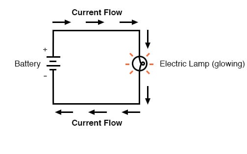
Remember that electrons can flow only when they have the opportunity to move in the space between the atoms of a material. This means that there can be electric current only where there exists a continuous path of conductive material providing a conduit for electrons to travel through. In the marble analogy, marbles can flow into the left-hand side of the tube (and, consequently, through the tube) if and only if the tube is open on the right-hand side for marbles to flow out. If the tube is blocked on the right-hand side, the marbles will just “pile up” inside the tube, and marble “flow” will not occur. The same holds true for electric current: the continuous flow of electrons requires there be an unbroken path to permit that flow. Let’s look at a diagram to illustrate how this works:

A thin, solid line (as shown above) is the conventional symbol for a continuous piece of wire. Since the wire is made of a conductive material, such as copper, its constituent atoms have many free electrons which can easily move through the wire. However, there will never be a continuous or uniform flow of electrons within this wire unless they have a place to come from and a place to go. Let’s add a hypothetical electron “Source” and “Destination:”

Now, with the Electron Source pushing new electrons into the wire on the left-hand side, electron flow through the wire can occur (as indicated by the arrows pointing from left to right). However, the flow will be interrupted if the conductive path formed by the wire is broken:

Electrical Continuity
Since air is an insulating material, and an air gap separates the two pieces of wire, the once-continuous path has now been broken, and electrons cannot flow from Source to Destination. This is like cutting a water pipe in two and capping off the broken ends of the pipe: water can’t flow if there’s no exit out of the pipe. In electrical terms, we had a condition of electrical continuity when the wire was in one piece, and now that continuity is broken with the wire cut and separated.
If we were to take another piece of wire leading to the Destination and simply make physical contact with the wire leading to the Source, we would once again have a continuous path for electrons to flow. The two dots in the diagram indicate physical (metal-to-metal) contact between the wire pieces:

Now, we have continuity from the Source, to the newly-made connection, down, to the right, and up to the Destination. This is analogous to putting a “tee” fitting in one of the capped-off pipes and directing water through a new segment of pipe to its destination. Please take note that the broken segment of wire on the right-hand side has no electrons flowing through it because it is no longer part of a complete path from Source to Destination.
It is interesting to note that no “wear” occurs within wires due to this electric current, unlike water-carrying pipes which are eventually corroded and worn by prolonged flows. Electrons do encounter some degree of friction as they move, however, and this friction can generate heat in a conductor. This is a topic we’ll explore in much greater detail later.
- In conductive materials, the outer electrons in each atom can easily come or go and are called free electrons.
- In insulating materials, the outer electrons are not so free to move.
- All metals are electrically conductive.
- Dynamic electricity, or electric current, is the uniform motion of electrons through a conductor.
- Static electricity is unmoving (if on an insulator), accumulated charge formed by either an excess or deficiency of electrons in an object. It is typically formed by charge separation by contact and separation of dissimilar materials.
- For electrons to flow continuously (indefinitely) through a conductor, there must be a complete, unbroken path for them to move both into and out of that conductor.
2.3 What Are Electric Circuits?
You might have been wondering how charges can continuously flow in a uniform direction through wires without the benefit of these hypothetical Sources and Destinations. In order for the Source-and-Destination scheme to work, both would have to have an infinite capacity for charges in order to sustain a continuous flow!
Using the marble-and-tube analogy from the previous section on conductors, insulators, and electron flow, the marble source, and marble destination buckets would have to be infinitely large to contain enough marble capacity for a “flow” of marbles to be sustained.
What Is a Circuit?
The answer to this paradox is found in the concept of a circuit: a never-ending looped pathway for charge carriers. If we take a wire, or many wires, joined end-to-end, and loop it around so that it forms a continuous pathway, we have the means to support a uniform flow of charge without having to resort to infinite Sources and Destinations:

Each charge carrier advancing clockwise in this circuit pushes on the one in front of it, which pushes on the one in front of it, and so on, and so on, just like a hula-hoop filled with marbles. Now, we have the capability of supporting a continuous flow of charge indefinitely without the need for infinite supplies and dumps. All we need to maintain this flow is a continuous means of motivation for those charge carriers, which we’ll address in the next section of this chapter on voltage and current.
What Does it mean when a Circuit is broken?
Continuity is just as important in a circuit as it is in a straight piece of wire. Just as in the example with the straight piece of wire between the Source and Destination, any break in this circuit will prevent charge from flowing through it:

An important principle to realize here is that it doesn’t matter where the break occurs. Any discontinuity in the circuit will prevent charge flow throughout the entire circuit. Unless there is a continuous, unbroken loop of conductive material for charge carriers to flow through, a sustained flow simply cannot be maintained.

Review
- A circuit is an unbroken loop of conductive material that allows charge carriers to flow through continuously without beginning or end.
- If a circuit is “broken,” that means its conductive elements no longer form a complete path, and continuous charge flow cannot occur in it.
- The location of a break in a circuit is irrelevant to its inability to sustain continuous charge flow. Any break, anywhere in a circuit prevents the flow of charge carriers throughout the circuit.
2.4 Voltage and Current
As was previously mentioned, we need more than just a continuous path (i.e., a circuit) before a continuous flow of charge will occur: we also need some means to push these charge carriers around the circuit. Just like marbles in a tube or water in a pipe, it takes some kind of influencing force to initiate flow. With electrons, this force is the same force at work in static electricity: the force produced by an imbalance of electric charge.
If we take the examples of wax and wool which have been rubbed together, we find that the surplus of electrons in the wax (negative charge) and the deficit of electrons in the wool (positive charge) creates an imbalance of charge between them. This imbalance manifests itself as an attractive force between the two objects:

If a conductive wire is placed between the charged wax and wool, electrons will flow through it, as some of the excess electrons in the wax rush through the wire to get back to the wool, filling the deficiency of electrons there:

The imbalance of electrons between the atoms in the wax and the atoms in the wool creates a force between the two materials. With no path for electrons to flow from the wax to the wool, all this force can do is attract the two objects together.
Now that a conductor bridges the insulating gap, however, the force will provoke electrons to flow in a uniform direction through the wire, if only momentarily, until the charge in that area neutralizes and the force between the wax and wool diminishes.
The electric charge formed between these two materials by rubbing them together serves to store a certain amount of energy. This energy is not unlike the energy stored in a high reservoir of water that has been pumped from a lower-level pond:
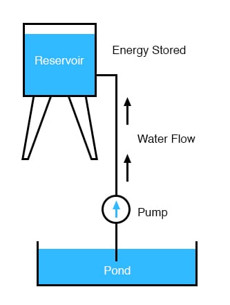
The influence of gravity on the water in the reservoir creates a force that attempts to move the water down to the lower level again. If a suitable pipe is run from the reservoir back to the pond, water will flow under the influence of gravity down from the reservoir, through the pipe:
It takes energy to pump that water from the low-level pond to the high-level reservoir, and the movement of water through the piping back down to its original level constitutes a releasing of energy stored from the previous pumping.
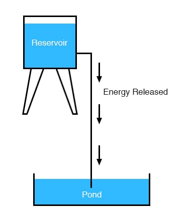
If the water is pumped to an even higher level, it will take even more energy to do so, thus more energy will be stored, and more energy released if the water is allowed to flow through a pipe back down again:

Electrons are not much different. If we rub wax and wool together, we “pump” electrons away from their normal “levels,” creating a condition where a force exists between the wax and wool, as the electrons seek to re-establish their former positions (and balance within their respective atoms). The force attracting electrons back to their original positions around the positive nuclei of their atoms is analogous to the force gravity exerts on the water in the reservoir, trying to draw it down to its former level. Just as the pumping of water to a higher level results in energy being stored, “pumping” electrons to create an electric charge imbalance results in a certain amount of energy being stored in that imbalance. And, just as providing a way for water to flow back down from the heights of the reservoir results in a release of that stored energy, providing a way for electrons to flow back to their original “levels” results in a release of stored energy.
When the charge carriers are poised in that static condition (just like water sitting still, high in a reservoir), the energy stored there is called potential energy, because it has the possibility (potential) of release that has not been fully realized yet.
Understanding the Concept of Voltage
When the charge carriers are poised in that static condition (just like water sitting still, high in a reservoir), the energy stored there is called potential energy, because it has the possibility (potential) of release that has not been fully realized yet.
When you scuff your rubber-soled shoes against a fabric carpet on a dry day, you create an imbalance of electric charge between yourself and the carpet. The action of scuffing your feet stores energy in the form of an imbalance of charges forced from their original locations. This charge (static electricity) is stationary, and you won’t realize that energy is being stored at all. However, once you place your hand against a metal doorknob (with lots of electron mobility to neutralize your electric charge), that stored energy will be released in the form of a sudden flow of charge through your hand, and you will perceive it as an electric shock!
This potential energy, stored in the form of an electric charge imbalance and capable of provoking charge carriers to flow through a conductor, can be expressed as a term called voltage, which technically is a measure of potential energy per unit charge or something a physicist would call specific potential energy.
The Definition of Voltage
Defined in the context of static electricity, voltage is the measure of work required to move a unit charge from one location to another, against the force which tries to keep electric charges balanced. In the context of electrical power sources, voltage is the amount of potential energy available (work to be done) per unit charge, to move charges through a conductor. Because voltage is an expression of potential energy, representing the possibility or potential for energy release as the charge moves from one “level” to another, it is always referenced between two points. Consider the water reservoir analogy:
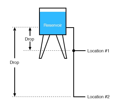
Because of the difference in the height of the drop, there’s potential for much more energy to be released from the reservoir through the piping to location 2 than to location 1. The principle can be intuitively understood in dropping a rock: which results in a more violent impact, a rock dropped from a height of one foot, or the same rock dropped from a height of one mile?
Obviously, the drop of greater height results in greater energy released (a more violent impact). We cannot assess the amount of stored energy in a water reservoir simply by measuring the volume of water any more than we can predict the severity of a falling rock’s impact simply from knowing the weight of the rock: in both cases we must also consider how far these masses will drop from their initial height. The amount of energy released by allowing a mass to drop is relative to the distance between its starting and ending points. Likewise, the potential energy available for moving charge carriers from one point to another is relative to those two points. Therefore, voltage is always expressed as a quantity between two points.
Interestingly enough, the analogy of a mass potentially “dropping” from one height to another is such an apt model that voltage between two points is sometimes called a voltage drop.
Generating Voltage
Voltage can be generated by means other than rubbing certain types of materials against each other. Chemical reactions, radiant energy, and the influence of magnetism on conductors are a few ways in which voltage may be produced. Respective examples of these three sources of voltage are batteries, solar cells, and generators (such as the “alternator” unit under the hood of your automobile). For now, we won’t go into detail as to how each of these voltage sources works—more important is that we understand how voltage sources can be applied to create charge flow in an electric circuit.
Let’s take the symbol for a chemical battery and build a circuit step by step:

How Do Voltage Sources Work?
Any source of voltage, including batteries, have two points for electrical contact. In this case, we have point 1 and point 2 in the above diagram. The horizontal lines of varying length indicate that this is a battery, and they further indicate the direction in which this battery’s voltage will try to push charge carriers through a circuit. The fact that the horizontal lines in the battery symbol appear separated (and thus unable to serve as a path for charge flow) is no cause for concern: in real life, those horizontal lines represent metallic plates immersed in a liquid or semi-solid material that not only conducts charges but also generates the voltage to push them along by interacting with the plates.
Notice the little “+” and “-” signs to the immediate left of the battery symbol. The negative (-) end of the battery is always the end with the shortest dash, and the positive (+) end of the battery is always the end with the longest dash. The positive end of a battery is the end that tries to push charge carriers out of it (remember that by convention we think of charge carriers as being positively charged, even though electrons are negatively charged). Likewise, the negative end is the end that tries to attract the charge carriers.
With the “+” and “-” ends of the battery not connected to anything, there will be voltage between those two points, but there will be no charge flow through the battery because there is no continuous path through which charge carriers can move.

The same principle holds true for the water reservoir and pump analogy: without a return pipe back to the pond, stored energy in the reservoir cannot be released in the form of water flow. Once the reservoir is completely filled up, no flow can occur, no matter how much pressure the pump may generate. There needs to be a complete path (circuit) for water to flow from the pond to the reservoir, and back to the pond in order for continuous flow to occur.
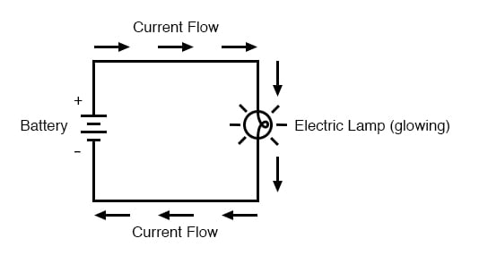
We can provide such a path for the battery by connecting a piece of wire from one end of the battery to the other. Forming a circuit with a loop of wire, we will initiate a continuous flow of charge in a clockwise direction:

Understanding the Concept of Electric Current
As long as the battery continues to produce voltage and the continuity of the electrical path isn’t broken, charge carriers will continue to flow in the circuit. Following the metaphor of water moving through a pipe, this continuous, uniform flow of charge through the circuit is called a current. So long as the voltage source keeps “pushing” in the same direction, the charge carriers will continue to move in the same direction in the circuit. This single-direction flow of current is called a Direct Current, or DC. In the second volume of this book series, electric circuits are explored where the direction of current switches back and forth: Alternating Current, or AC. But for now, we’ll just concern ourselves with DC circuits.
Because electric current is composed of individual charge carriers flowing in unison through a conductor by moving along and pushing on the charge carriers ahead, just like marbles through a tube or water through a pipe, the amount of flow throughout a single circuit will be the same at any point. If we were to monitor a cross-section of the wire in a single circuit, counting the charge carriers flowing by, we would notice the exact same quantity per unit of time as in any other part of the circuit, regardless of conductor length or conductor diameter.
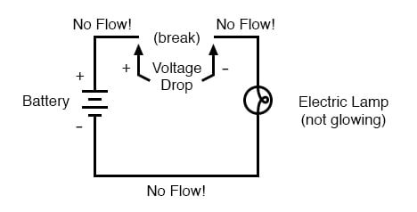
If we break the circuit’s continuity at any point, the electric current will cease in the entire loop, and the full voltage produced by the battery will be manifested across the break, between the wire ends that used to be connected:

What is the Polarity of a Voltage Drop?
Notice the “+” and “-” signs drawn at the ends of the break in the circuit, and how they correspond to the “+” and “-” signs next to the battery’s terminals. These markers indicate the direction that the voltage attempts to push the current, that potential direction commonly referred to as polarity. Remember that voltage is always relative between two points. Because of this fact, the polarity of a voltage drop is also relative between two points: whether a point in a circuit gets labeled with a “+” or a “-” depends on the other point to which it is referenced. Take a look at the following circuit, where each corner of the loop is marked with a number for reference:

With the circuit’s continuity broken between points 2 and 3, the polarity of the voltage dropped between points 2 and 3 is “+” for point 2 and “-” for point 3. The battery’s polarity (1 “+” and 4 “-”) is trying to push the current through the loop clockwise from 1 to 2 to 3 to 4 and back to 1 again.
Now let’s see what happens if we connect points 2 and 3 back together again, but place a break in the circuit between points 3 and 4:

With the break between 3 and 4, the polarity of the voltage drop between those two points is “-” for 4 and “+” for 3. Take special note of the fact that point 3’s “sign” is opposite of that in the first example, where the break was between points 2 and 3 (where point 3 was labeled “-”). It is impossible for us to say that point 3 in this circuit will always be either “+” or “-”, because polarity, like voltage itself, is not specific to a single point, but is always relative between two points!
- Charge carriers can be motivated to flow through a conductor by the same force manifested in static electricity.
- Voltage is the measure of specific potential energy (potential energy per unit charge) between two locations. In layman’s terms, it is the measure of “push” available to motivate the charge.
- Voltage, as an expression of potential energy, is always relative between two locations, or points. Sometimes it is called a voltage “drop.”
- When a voltage source is connected to a circuit, the voltage will cause a uniform flow of charge carriers through that circuit called a current.
- In a single (one loop) circuit, the amount of current at any point is the same as the amount of current at any other point.
- If a circuit containing a voltage source is broken, the full voltage of that source will appear across the points of the break.
- The +/- orientation of a voltage drop is called the polarity. It is also relative between two points.
2.5 Resistance
The circuit in the previous section is not a very practical one. In fact, it can be quite dangerous to build (directly connecting the poles of a voltage source together with a single piece of wire). The reason it is dangerous is that the magnitude of electric current may be very large in such a short circuit, and the release of energy may be very dramatic (usually in the form of heat).
Usually, electric circuits are constructed in such a way as to make practical use of that released energy, in as safe a manner as possible.
The Current Flow through Filament of the Lamp
One practical and popular use of electric current is for the operation of electric lighting. The simplest form of electric lamp is a tiny metal “filament” inside of a clear glass bulb, which glows white-hot (“incandesces”) with heat energy when sufficient electric current passes through it. Like the battery, it has two conductive connection points, one for current to enter and the other for current to exit.
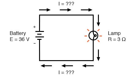
Connected to a source of voltage, an electric lamp circuit looks something like this:
As the current works its way through the thin metal filament of the lamp, it encounters more opposition to motion than it typically would in a thick piece of wire. This opposition to electric current depends on the type of material, its cross-sectional area, and its temperature. It is technically known as resistance. (It can be said that conductors have low resistance and insulators have very high resistance.) This resistance serves to limit the amount of current through the circuit with a given amount of voltage supplied by the battery, as compared with the “short circuit” where we had nothing but a wire joining one end of the voltage source (battery) to the other.
When the current moves against the opposition of resistance, “friction” is generated. Just like mechanical friction, the friction produced by the current flowing against a resistance manifests itself in the form of heat. The concentrated resistance of a lamp’s filament results in a relatively large amount of heat energy dissipated at that filament. This heat energy is enough to cause the filament to glow white-hot, producing light, whereas the wires connecting the lamp to the battery (which have much lower resistance) hardly even get warm while conducting the same amount of current.
As in the case of the short circuit, if the continuity of the circuit is broken at any point, current flow stops throughout the entire circuit. With a lamp in place, this means that it will stop glowing:
As before, with no flow of current, the entire potential (voltage) of the battery is available across the break, waiting for the opportunity of a connection to bridge across that break and permit current flow again. This condition is known as an open circuit, where a break in the continuity of the circuit prevents current throughout.
All it takes is a single break in continuity to “open” a circuit. Once any breaks have been connected once again and the continuity of the circuit re-established, it is known as a closed circuit.
The Basis for Switching Lamps
What we see here is the basis for switching lamps on and off by remote switches. Because any break in a circuit’s continuity results in current stopping throughout the entire circuit, we can use a device designed to intentionally break that continuity (called a switch), mounted at any convenient location that we can run wires to, to control the flow of current in the circuit:

This is how a switch mounted on the wall of a house can control a lamp that is mounted down a long hallway, or even in another room, far away from the switch. The switch itself is constructed of a pair of conductive contacts (usually made of some kind of metal) forced together by a mechanical lever actuator or push button. When the contacts touch each other, the current is able to flow from one to the other and the circuit’s continuity is established. When the contacts are separated, current flow from one to the other is prevented by the insulation of the air between, and the circuit’s continuity is broken.
The Knife Switch
Perhaps the best kind of switch to show for illustration of the basic principle is the “knife” switch:

A knife switch is nothing more than a conductive lever, free to pivot on a hinge, coming into physical contact with one or more stationary contact points which are also conductive.
The switch shown in the above illustration is constructed on a porcelain base (an excellent insulating material), using copper (an excellent conductor) for the “blade” and contact points. The handle is plastic to insulate the operator’s hand from the conductive blade of the switch when opening or closing it.
Here is another type of knife switch, with two stationary contacts instead of one:

The particular knife switch shown here has one “blade” but two stationary contacts, meaning that it can make or break more than one circuit. For now, this is not terribly important to be aware of, just the basic concept of what a switch is and how it works. Knife switches are great for illustrating the basic principle of how a switch works, but they present distinct safety problems when used in high-power electric circuits. The exposed conductors in a knife switch make accidental contact with the circuit a distinct possibility, and any sparking that may occur between the moving blade and the stationary contact is free to ignite any nearby flammable materials. Most modern switch designs have their moving conductors and contact points sealed inside an insulating case in order to mitigate these hazards. A photograph of a few modern switch types show how the switching mechanisms are much more concealed than with the knife design:

Opened and Closed Circuits
In keeping with the “open” and “closed” terminology of circuits, a switch that is making contact from one connection terminal to the other (example: a knife switch with the blade fully touching the stationary contact point) provides continuity for current to flow through and is called a closed switch.
Conversely, a switch that is breaking continuity (example: a knife switch with the blade not touching the stationary contact point) won’t allow current to pass through and is called an open switch. This terminology is often confusing to the new student of electronics because the words “open” and “closed” are commonly understood in the context of a door, where “open” is equated with free passage and “closed” with blockage. With electrical switches, these terms have opposite meanings: “open” means no flow while “closed” means free passage of electric current.
- Resistance is the measure of opposition to electric current.
- A short circuit is an electric circuit offering little or no resistance to the flow of current. Short circuits are dangerous with high voltage power sources because the high currents encountered can cause large amounts of heat energy to be released.
- An open circuit is one where the continuity has been broken by an interruption in the path for current to flow.
- A closed-circuit is one that is complete, with good continuity throughout.
- A device designed to open or close a circuit under controlled conditions is called a switch.
- The terms “open” and “closed” refer to switches as well as entire circuits. An open switch is one without continuity: current cannot flow through it. A closed switch is one that provides a direct (low resistance) path for current to flow through.
2.6 Resistors
Because the relationship between voltage, current, and resistance in any circuit is so regular, we can reliably control any variable in a circuit simply by controlling the other two. Perhaps the easiest variable in any circuit to control is its resistance. This can be done by changing the material, size, and shape of its conductive components (remember how the thin metal filament of a lamp created more electrical resistance than a thick wire?).
What is a Resistor?
Special components called resistors are made for the express purpose of creating a precise quantity of resistance for insertion into a circuit. They are typically constructed of metal wire or carbon and engineered to maintain a stable resistance value over a wide range of environmental conditions. Unlike lamps, they do not produce light, but they do produce heat as electric power is dissipated by them in a working circuit. Typically, though, the purpose of a resistor is not to produce usable heat, but simply to provide a precise quantity of electrical resistance.
Resistor Schematic Symbols and Values
The most common schematic symbol for a resistor is a zig-zag line:

Resistor values in ohms are usually shown as an adjacent number, and if several resistors are present in a circuit, they will be labeled with a unique identifier number such as R1, R2, R3, etc. As you can see, resistor symbols can be shown either horizontally or vertically:

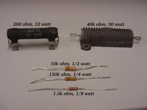
Real resistors look nothing like the zig-zag symbol. Instead, they look like small tubes or cylinders with two wires protruding for connection to a circuit. Here is a sampling of different kinds and sizes of resistors:
In keeping more with their physical appearance, an alternative schematic symbol for a resistor looks like a small, rectangular box:

Resistors can also be shown to have varying rather than fixed resistances. This might be for the purpose of describing an actual physical device designed for the purpose of providing an adjustable resistance, or it could be to show some component that just happens to have an unstable resistance:
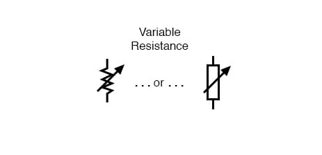
In fact, any time you see a component symbol drawn with a diagonal arrow through it, that component has a variable rather than a fixed value. This symbol “modifier” (the diagonal arrow) is a standard electronic symbol convention.
Variable Resistors
Variable resistors must have some physical means of adjustment, either a rotating shaft or lever that can be moved to vary the amount of electrical resistance. Here is a photograph showing some devices called potentiometers, which can be used as variable resistors:

Power Rating of Resistors
Because resistors dissipate heat energy as the electric currents through them overcome the “friction” of their resistance, resistors are also rated in terms of how much heat energy they can dissipate without overheating and sustaining damage. Naturally, this power rating is specified in the physical unit of “watts.” Most resistors found in small electronic devices such as portable radios are rated at 1/4 (0.25) watt or less. The power rating of any resistor is roughly proportional to its physical size. Note in the first resistor photograph how the power ratings relate with size: the bigger the resistor, the higher its power dissipation rating. Also, note how resistances (in ohms) have nothing to do with size!
Although it may seem pointless now to have a device doing nothing but resisting electric current, resistors are extremely useful devices in circuits. Because they are simple and so commonly used throughout the world of electricity and electronics, we’ll spend a considerable amount of time analyzing circuits composed of nothing but resistors and batteries.
How are Resistors Useful?
For a practical illustration of resistors’ usefulness, examine the photograph below. It is a picture of a printed circuit board, or PCB: an assembly made of sandwiched layers of insulating phenolic fiber-board and conductive copper strips, into which components may be inserted and secured by a low-temperature welding process called “soldering.” The various components on this circuit board are identified by printed labels. Resistors are denoted by any label beginning with the letter “R”.

This particular circuit board is a computer accessory called a “modem,” which allows digital information transfer over telephone lines. There are at least a dozen resistors (all rated at 1/4 watt power dissipation) that can be seen on this modem’s board. Every one of the black rectangles (called “integrated circuits” or “chips”) contain their own array of resistors for their internal functions, as well. Another circuit board example shows resistors packaged in even smaller units, called “surface mount devices.” This particular circuit board is the underside of a personal computer hard disk drive, and once again the resistors soldered onto it are designated with labels beginning with the letter “R”:
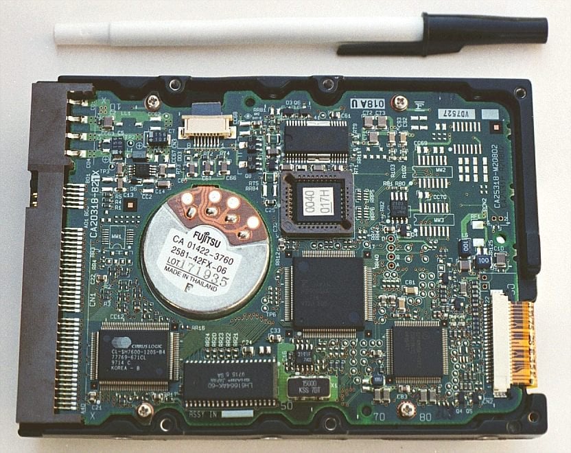
There are over one hundred surface-mount resistors on this circuit board, and this count, of course, does not include the number of resistors internal to the black “chips.” These two photographs should convince anyone that resistors—devices that “merely” oppose the flow of electric current—are very important components in the realm of electronics!
“Load” on Schematic Diagrams
In schematic diagrams, resistor symbols are sometimes used to illustrate any general type of device in a circuit doing something useful with electrical energy. Any non-specific electrical device is generally called a load, so if you see a schematic diagram showing a resistor symbol labeled “load,” especially in a tutorial circuit diagram explaining some concept unrelated to the actual use of electrical power, that symbol may just be a kind of shorthand representation of something else more practical than a resistor.
Analyzing Resistor Circuits
To summarize what we’ve learned in this lesson, let’s analyze the following circuit, determining all that we can from the information given:
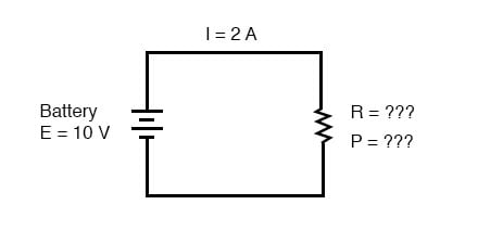
All we’ve been given here to start with is the battery voltage (10 volts) and the circuit current (2 amps). We don’t know the resistor’s resistance in ohms or the power dissipated by it in watts. Surveying our array of Ohm’s Law equations, we find two equations that give us answers from known quantities of voltage and current:
Ohm’s Law
[latex]R=\frac{E}{I}\tag{2.1}[/latex]
Power Equation
[latex]P = IE\tag{2.2}[/latex]
Inserting the known quantities of voltage (E) and current (I) into these two equations, we can determine circuit resistance (R) and power dissipation (P):
Ohm’s Law:
[latex]R\:=\frac{10V}{2A}= 5\Omega[/latex]
Power Law:
[latex]P = (2A)(10V)= (20W)[/latex]
For the circuit conditions of 10 volts and 2 amps, the resistor’s resistance must be 5 Ω. If we were designing a circuit to operate at these values, we would have to specify a resistor with a minimum power rating of 20 watts, or else it would overheat and fail.
Resistor Materials
Resistors can be found in a variety of different materials, each one with its own properties and specific areas of use. Most electrical engineers use the types found below:
Wire wound (WW) Resistors
Wire Wound Resistors are manufactured by winding resistance wire around a non-conductive core in a spiral. They are typically produced for high precision and power applications. The core is usually made of ceramic or fiberglass and the resistance wire is made of nickel-chromium alloy and is not suitable for applications with frequencies higher than 50kHz. Low noise and stability with respect to temperature variations are standard characteristics of Wire Wound Resistors. Resistance values are available from 0.1 up to 100 kW, with accuracies between 0.1% and 20%.
Metal Film Resistors
Nichrome or tantalum nitride is typically used for metal film resistors. A combination of a ceramic material and a metal typically make up the resistive material. The resistance value is changed by cutting a spiral pattern in the film, much like a carbon film with a laser or abrasive. Metal film resistors are usually less stable over temperature than wire wound resistors but handle higher frequencies better.
Metal Oxide Film Resistors
Metal oxide resistors use metal oxides such as tin oxide, making them slightly different from metal film resistors. These resistors are reliable and stable and operate at higher temperatures than metal film resistors. Because of this, metal oxide film resistors are used in applications that require high endurance.
Foil Resistors
Developed in the 1960s, the foil resistor is still one of the most accurate and stable types of resistors that you’ll find and are used for applications with high precision requirements. A ceramic substrate that has a thin bulk metal foil cemented to it makes up the resistive element. Foil Resistors feature a very low-temperature coefficient of resistance.
Carbon Composition (CCR) Resistors
Until the 1960s Carbon Composition Resistors were the standard for most applications. They are reliable, but not very accurate (their tolerance cannot be better than about 5%). A mixture of fine carbon particles and non-conductive ceramic material are used for the resistive element of CCR Resistors. The substance is molded into the shape of a cylinder and baked. The dimensions of the body and the ratio of carbon to ceramic material determine the resistance value. More carbon used in the process means there will be a lower resistance. CCR resistors are still useful for certain applications because of their ability to withstand high energy pulses, a good example application would be in a power supply.
Carbon Film Resistors
Carbon film resistors have a thin carbon film (with a spiral cut in the film to increase the resistive path) on an insulating cylindrical core. This allows for the resistance value to be more accurate and also increases the resistance value. Carbon film resistors are much more accurate than carbon composition resistors. Special carbon film resistors are used in applications that require high pulse stability.
Performance Indicators (KPIs)
The KPIs for each resistor material can be found below:
| Characteristic | Metal Film | Thick Metal Film | Precision Metal Film | Carbon Composition | Carbon Film |
|---|---|---|---|---|---|
| Temp. range | -55+125 | -55+130 | -55+155 | -40+105 | .55+155 |
| Max. temp. coeff. | 100 | 100 | 15 | 1200 | 250-1000 |
| Vmax | 200-350 | 250 | 200 | 350-500 | 350-500 |
| Noise (μV per volt of applied DC) | 0.5 | 0.1 | 0.1 | 4 (100K) | 5 (100K) |
| R Insul. | 10000 | 10000 | 10000 | 10000 | 10000 |
| Solder (change % in resistance value) | 0.20% | 0.15% | 0.02% | 2% | 0.50% |
| Damp heat (change % in resistance value) | 0.50% | 1% | 0.50% | 15% | 3.50% |
| Shelf life (change % in resistance value) | 0.10% | 0.10% | 0.00% | 5% | 2% |
| Full rating (2000h at 70 degC) | 1% | 1% | 0.03% | 10% | 4% |
Review
- Devices called resistors are built to provide precise amounts of resistance in electric circuits. Resistors are rated both in terms of their resistance (ohms) and their ability to dissipate heat energy (watts).
- Resistor resistance ratings cannot be determined from the physical size of the resistor(s) in question, although approximate power ratings can. The larger the resistor is the more power it can safely dissipate without suffering damage.
- Any device that performs some useful tasks with electric power is generally known as a load. Sometimes resistor symbols are used in schematic diagrams to designate a non-specific load, rather than an actual resistor.
2.7 Voltage and Current in a Practical Circuit
Because it takes energy to force charge to flow against the opposition of resistance, there will be voltage manifested (or “dropped”) between any points in a circuit with resistance between them.
It is important to note that although the amount of current (i.e., the quantity of charge moving past a given point every second) is uniform in a simple circuit, the amount of voltage (potential energy per unit charge) between different sets of points in a single circuit may vary considerably:

Take this circuit as an example. If we label four points in this circuit with the numbers 1, 2, 3, and 4, we will find that the amount of current conducted through the wire between points 1 and 2 is exactly the same as the amount of current conducted through the lamp (between points 2 and 3). This same quantity of current passes through the wire between points 3 and 4, and through the battery (between points 1 and 4).
However, we will find the voltage appearing between any two of these points to be directly proportional to the resistance within the conductive path between those two points, given that the amount of current along any part of the circuit’s path is the same (which, for this simple circuit, it is).
In a normal lamp circuit, the resistance of a lamp will be much greater than the resistance of the connecting wires, so we should expect to see a substantial amount of voltage between points 2 and 3, with very little between points 1 and 2, or between 3 and 4. The voltage between points 1 and 4, of course, will be the full amount of “force” offered by the battery, which will be only slightly greater than the voltage across the lamp (between points 2 and 3).
This, again, is analogous to the water reservoir system:

Between points 2 and 3, where the falling water is releasing energy at the water-wheel, there is a difference of pressure between the two points, reflecting the opposition to the flow of water through the water-wheel. From point 1 to point 2, or from point 3 to point 4, where water is flowing freely through reservoirs with little opposition, there is little or no difference of pressure (no potential energy). However, the rate of water flow in this continuous system is the same everywhere (assuming the water levels in both pond and reservoir are unchanging): through the pump, through the water-wheel, and through all the pipes.
So it is with simple electric circuits: current flow is the same at every point in the circuit, although voltages may differ between different sets of points
2.8 Ohm’s Law – How Voltage, Current, and Resistance Relate
The first, and perhaps most important, the relationship between current, voltage, and resistance is called Ohm’s Law, discovered by Georg Simon Ohm and published in his 1827 paper, The Galvanic Circuit Investigated Mathematically.
Voltage, Current, and Resistance
An electric circuit is formed when a conductive path is created to allow the electric charge to continuously move. This continuous movement of electric charge through the conductors of a circuit is called a current, and it is often referred to in terms of “flow,” just like the flow of a liquid through a hollow pipe.
The force motivating charge carriers to “flow” in a circuit is called voltage. Voltage is a specific measure of potential energy that is always relative between two points. When we speak of a certain amount of voltage being present in a circuit, we are referring to the measurement of how much potential energy exists to move charge carriers from one particular point in that circuit to another particular point. Without reference to two particular points, the term “voltage” has no meaning.
Current tends to move through the conductors with some degree of friction, or opposition to the motion. This opposition to motion is more properly called resistance. The amount of current in a circuit depends on the amount of voltage and the amount of resistance in the circuit to oppose current flow. Just like voltage, resistance is a quantity relative between two points. For this reason, the quantities of voltage and resistance are often stated as being “between” or “across” two points in a circuit.
Units of Measurement: Volt, Amp, and Ohm
To be able to make meaningful statements about these quantities in circuits, we need to be able to describe their quantities in the same way that we might quantify mass, temperature, volume, length, or any other kind of physical quantity. For mass, we might use the units of “kilogram” or “gram.” For temperature, we might use degrees Fahrenheit or degrees Celsius. Here are the standard units of measurement for electrical current, voltage, and resistance:
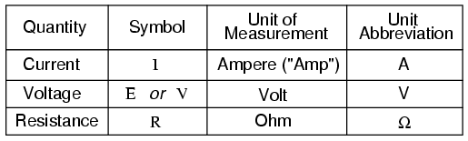
The “symbol” given for each quantity is the standard alphabetical letter used to represent that quantity in an algebraic equation. Standardized letters like these are common in the disciplines of physics and engineering and are internationally recognized. The “unit abbreviation” for each quantity represents the alphabetical symbol used as a shorthand notation for its particular unit of measurement. And, yes, that strange-looking “horseshoe” symbol is the capital Greek letter Ω, just a character in a foreign alphabet (apologies to any Greek readers here).
Each unit of measurement is named after a famous experimenter in electricity: The amp after the Frenchman Andre M. Ampere, the volt after the Italian Alessandro Volta, and the ohm after the German Georg Simon Ohm.
The mathematical symbol for each quantity is meaningful as well. The “R” for resistance and the “V” for voltage are both self-explanatory, whereas “I” for current seems a bit weird. The “I” is thought to have been meant to represent “Intensity” (of charge flow), and the other symbol for voltage, “E,” stands for “Electromotive force.” From what research I’ve been able to do, there seems to be some dispute over the meaning of “I.” The symbols “E” and “V” are interchangeable for the most part, although some texts reserve “E” to represent voltage across a source (such as a battery or generator) and “V” to represent voltage across anything else.
All of these symbols are expressed using capital letters, except in cases where a quantity (especially voltage or current) is described in terms of a brief period of time (called an “instantaneous” value). For example, the voltage of a battery, which is stable over a long period of time, will be symbolized with a capital letter “E,” while the voltage peak of a lightning strike at the very instant it hits a power line would most likely be symbolized with a lower-case letter “e” (or lower-case “v”) to designate that value as being at a single moment in time. This same lower-case convention holds true for current as well, the lower-case letter “i” representing current at some instant in time. Most direct-current (DC) measurements, however, being stable over time, will be symbolized with capital letters.
Coulomb and Electric Charge
One foundational unit of electrical measurement often taught in the beginnings of electronics courses but used infrequently afterward, is the unit of the coulomb, which is a measure of electric charge proportional to the number of electrons in an imbalanced state. One coulomb of charge is equal to 6,250,000,000,000,000,000 electrons. The symbol for electric charge quantity is the capital letter “Q,” with the unit of coulombs abbreviated by the capital letter “C.” It so happens that the unit for current flow, the amp, is equal to 1 coulomb of charge passing by a given point in a circuit in 1 second of time. Cast in these terms, the current is the rate of electric charge motion through a conductor.
As stated before, voltage is the measure of potential energy per unit charge available to motivate current flow from one point to another. Before we can precisely define what a “volt” is, we must understand how to measure this quantity we call “potential energy.” The general metric unit for energy of any kind is the joule, equal to the amount of work performed by a force of 1 newton exerted through a motion of 1 meter (in the same direction). In British units, this is slightly less than 3/4 pound of force exerted over a distance of 1 foot. Put in common terms, it takes about 1 joule of energy to lift a 3/4-pound weight 1 foot off the ground or to drag something a distance of 1 foot using a parallel pulling force of 3/4 pound. Defined in these scientific terms, 1 volt is equal to 1 joule of electric potential energy per (divided by) 1 coulomb of charge. Thus, a 9-volt battery releases 9 joules of energy for every coulomb of charge moved through a circuit.
These units and symbols for electrical quantities will become very important to know as we begin to explore the relationships between them in circuits.
Ohm’s Law Equations
Ohm’s principal discovery was that the amount of electric current through a metal conductor in a circuit is directly proportional to the voltage impressed across it, for any given temperature. Ohm expressed his discovery in the form of a simple equation, describing how voltage, current, and resistance interrelate:
In this algebraic expression, voltage (E) is equal to current (I) multiplied by resistance (R). Using algebra techniques, we can manipulate this equation into two variations, solving for I and for R, respectively:
Analyzing Simple Circuits with Ohm’s Law
Let’s see how these equations might work to help us analyze simple circuits:
In the above circuit, there is only one source of voltage (the battery, on the left) and only one source of resistance to current (the lamp, on the right). This makes it very easy to apply Ohm’s Law. If we know the values of any two of the three quantities (voltage, current, and resistance) in this circuit, we can use Ohm’s Law to determine the third.
Example 2.2
In this first example, we will calculate the amount of current (I) in a circuit, given values of voltage (E) and resistance (R):
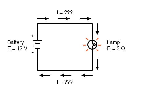
What is the amount of current (I) in this circuit?
[latex]I = \frac{E}{R}[/latex] [latex]= \frac{12V}{3\Omega}= 4A[/latex]
Example 2.3
In this second example, we will calculate the amount of resistance (R) in a circuit, given values of voltage (E) and current (I):
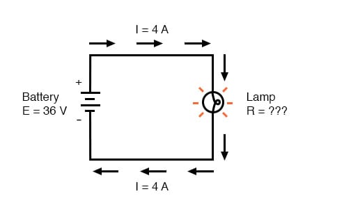
What is the amount of resistance (R) offered by the lamp?
[latex]R = \frac{E}{I}[/latex] [latex]= \frac{36V}{4A}= 9\Omega[/latex]
Example 2.4
In the last example, we will calculate the amount of voltage supplied by a battery, given values of current (I) and resistance (R):
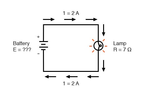
What is the amount of voltage provided by the battery?
[latex]E = IR[/latex] [latex]= (2A)(7\Omega) =14V[/latex]
Ohm’s Law Triangle Technique
Ohm’s Law is a very simple and useful tool for analyzing electric circuits. It is used so often in the study of electricity and electronics that it needs to be committed to memory by the serious student. For those who are not yet comfortable with algebra, there’s a trick to remembering how to solve for any one quantity, given the other two. First, arrange the letters E, I, and R in a triangle like this:
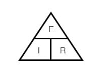
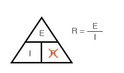
If you know E and I, and wish to determine R, just eliminate R from the picture and see what’s left:
If you know E and R, and wish to determine I, eliminate I and see what’s left:
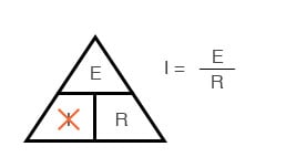
Lastly, if you know I and R, and wish to determine E, eliminate E and see what’s left:

Eventually, you’ll have to be familiar with algebra to seriously study electricity and electronics, but this tip can make your first calculations a little easier to remember. If you are comfortable with algebra, all you need to do is commit E = IR to memory and derive the other two formulae from that when you need them!
- Voltage is measured in volts, symbolized by the letters “E” or “V”.
- Current is measured in amps, symbolized by the letter “I”.
- Resistance is measured in ohms, symbolized by the letter “R”.
- [latex]\text{Ohm’s Law: }E = IR[/latex] ; [latex]I = \frac{E}{R}[/latex]; [latex]R = \frac{E}{I}[/latex]
2.9 Calculating Electric Power
Learn the Power Formula
We’ve seen the formula for determining the power in an electric circuit: by multiplying the voltage in “volts” by the current in “amps” we arrive at an answer in “watts.” Let’s apply this to a circuit example:
Example 2.5

In the above circuit, we know we have a battery voltage of 18 volts and a lamp resistance of 3 Ω. Using Ohm’s Law to determine current, we get:
[latex]I = \frac{E}{R}[/latex] [latex]= \frac{18V}{3\Omega}= 6A[/latex]
Now that we know the current, we can take that value and multiply it by the voltage to determine power:
[latex]P = IE[/latex] [latex]= (6A)(18V)= 108W[/latex]
This tells us that the lamp is dissipating (releasing) 108 watts of power, most likely in the form of both light and heat.
Increasing the Battery’s Voltage
Let’s try taking that same circuit and increasing the battery’s voltage to see what happens. Intuition should tell us that the circuit current will increase as the voltage increases and the lamp resistance stays the same. Likewise, the power will increase as well:
Example 2.6
Now, the battery’s voltage is 36 volts instead of 18 volts. The lamp is still providing 3 Ω of electrical resistance to the flow of current. The current is now:
[latex]I = \frac{E}{R}[/latex] [latex]= \frac{36V}{3\Omega}= 12A[/latex]
Example 2.7
What does Increasing a Battery’s Voltage do to Power?
Notice that the power has increased just as we might have suspected, but it increased quite a bit more than the current. Why is this? Because power is a function of voltage multiplied by current, and both voltage and current doubled from their previous values, the power will increase by a factor of 2 x 2, or 4. You can check this by dividing 432 watts by 108 watts and seeing that the ratio between them is indeed 4.
Using algebra again to manipulate the formula, we can take our original power formula and modify it for applications where we don’t know both voltage and current:
If we only know voltage (E) and resistance (R):
If, [latex]I = \frac{E}{R}[/latex] and [latex]P = IE[/latex]
then, [latex]P = ( \frac{E}{R}[/latex]) [latex]E[/latex] or [latex]P = \frac{E^{2} }{R}[/latex]
If we only know current (I) and resistance (R):
If, [latex]E = IR[/latex] and [latex]P = IE[/latex]
then, [latex]P = I(IR)[/latex] or [latex]P = I^{2} R[/latex]
Joule’s Law Vs. Ohm’s Law
A historical note: it was James Prescott Joule, not Georg Simon Ohm, who first discovered the mathematical relationship between power dissipation and current through a resistance. This discovery, published in 1841, followed the form of the last equation (P = I2R) and is properly known as Joule’s Law. However, these power equations are so commonly associated with the Ohm’s Law equations relating voltage, current, and resistance (E=IR; I=E/R; and R=E/I) that they are frequently credited to Ohm.
Power Equations
[latex]P = IE[/latex]
[latex]P = \frac{E^{2} }{R}[/latex]
[latex]P = I^{2} R[/latex]
Power measured in watts, symbolized by the letter “W”.
Joule’s Law:
[latex]P = I^{2} R[/latex]
[latex]P = IE[/latex]
[latex]P = \frac{E^{2} }{R}[/latex]
2.9 Circuit Wiring
So far, we’ve been analyzing single-battery, single-resistor circuits with no regard for the connecting wires between the components, so long as a complete circuit is formed. Does the wire length or circuit “shape” matter to our calculations? Let’s look at a couple of circuit diagrams and find out:
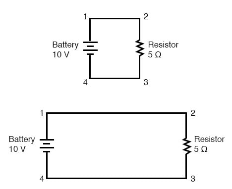
When we draw wires connecting points in an electric circuit, we usually assume those wires have negligible resistance. As such, they contribute no appreciable effect to the overall resistance of the circuit, and so the only resistance we have to contend with is the resistance in the components. In the above circuits, the only resistance comes from the 5 Ω resistors, so that is all we will consider in our calculations. In real life, metal wires actually do have resistance (and so do power sources!), but those resistances are generally so much smaller than the resistance present in the other circuit components that they can be safely ignored. Exceptions to this rule exist in power system wiring, where even very small amounts of conductor resistance can create significant voltage drops given normal (high) levels of current.
Electrically Common Points in a Circuit
If connecting wire resistance is very little or none, we can regard the connected points in a circuit as being electrically common. That is, points 1 and 2 in the above circuits may be physically joined close together or far apart, and it doesn’t matter for any voltage or resistance measurements relative to those points. The same goes for points 3 and 4. It is as if the ends of the resistor were attached directly across the terminals of the battery, so far as our Ohm’s Law calculations and voltage measurements are concerned. This is useful to know, because it means you can re-draw a circuit diagram or re-wire a circuit, shortening or lengthening the wires as desired without appreciably impacting the circuit’s function. All that matters is that the components attach to each other in the same sequence.
It also means that voltage measurements between sets of “electrically common” points will be the same. That is, the voltage between points 1 and 4 (directly across the battery) will be the same as the voltage between points 2 and 3 (directly across the resistor). Take a close look at the following circuit, and try to determine which points are common to each other:
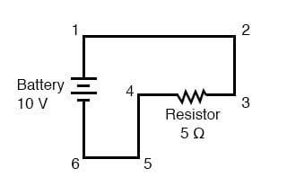
Here, we only have 2 components excluding the wires: the battery and the resistor. Though the connecting wires take a convoluted path in forming a complete circuit, there are several electrically common points in the current path. Points 1, 2, and 3 are all common to each other because they’re directly connected together by wire. The same goes for points 4, 5, and 6.
The voltage between points 1 and 6 is 10 volts, coming straight from the battery. However, since points 5 and 4 are common to 6, and points 2 and 3 common to 1, that same 10 volts also exists between these other pairs of points:
- Between points 1 and 4 = 10 volts
- Between points 2 and 4 = 10 volts
- Between points 3 and 4 = 10 volts (directly across the resistor)
- Between points 1 and 5 = 10 volts Between points 2 and 5 = 10 volts
- Between points 3 and 5 = 10 volts Between points 1 and 6 = 10 volts (directly across the battery)
- Between points 2 and 6 = 10 volts Between points 3 and 6 = 10 volts
Since electrically common points are connected together by (zero resistance) wire, there is no significant voltage drop between them regardless of the amount of current conducted from one to the next through that connecting wire. Thus, if we were to read voltages between common points, we should show (practically) zero:
- Between points 1 and 2 = 0 volts
- Points 1, 2, and 3 are Between points 2 and 3 = 0 volts electrically common
- Between points 1 and 3 = 0 volts
- Between points 4 and 5 = 0 volts
- Points 4, 5, and 6 are Between points 5 and 6 = 0 volts electrically common
- Between points 4 and 6 = 0 volts
Calculating the Voltage Drop with Ohm’s Law
This makes sense mathematically, too. With a 10 volt battery and a 5 Ω resistor, the circuit current will be 2 amps. With wire resistance being zero, the voltage drop across any continuous stretch of wire can be determined through Ohm’s Law as such:
[latex]E = IR[/latex]
[latex]E = (2A)(0\Omega)[/latex]
[latex]\textbf{E = 0V}[/latex]
It should be obvious that the calculated voltage drops across any uninterrupted length of wire in a circuit where the wire is assumed to have zero resistance will always be zero, no matter what the magnitude of current, since zero multiplied by anything equals zero.
Because common points in a circuit will exhibit the same relative voltage and resistance measurements, wires connecting common points are often labeled with the same designation. This is not to say that the terminal connection points are labeled the same, just the connecting wires. Take this circuit as an example:
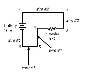
Points 1, 2, and 3 are all common to each other, so the wire connecting point 1 to 2 is labeled the same (wire 2) as the wire connecting point 2 to 3 (wire 2). In a real circuit, the wire stretching from point 1 to 2 may not even be the same color or size as the wire connecting point 2 to 3, but they should bear the exact same label. The same goes for the wires connecting points 6, 5, and 4.
Voltage Drop Should Equal Zero in Common Points
Knowing that electrically common points have zero voltage drop between them is a valuable troubleshooting principle. If I measure for voltage between points in a circuit that are supposed to be common to each other, I should read zero. If, however, I read substantial voltage between those two points, then I know with certainty that they cannot be directly connected together. If those points are supposed to be electrically common but they register otherwise, then I know that there is an “open failure” between those points.
Zero Voltage Technically Means Negligible Voltage
One final note: for most practical purposes, wire conductors can be assumed to possess zero resistance from end to end. In reality, however, there will always be some small amount of resistance encountered along the length of a wire, unless it’s a superconducting wire. Knowing this, we need to bear in mind that the principles learned here about electrically common points are all valid to a large degree, but not to an absolute degree. That is, the rule that electrically common points are guaranteed to have zero voltage between them is more accurately stated as such: electrically common points will have very little voltage dropped between them. That small, virtually unavoidable trace of resistance found in any piece of connecting wire is bound to create a small voltage across the length of it as current is conducted through. So long as you understand that these rules are based upon ideal conditions, you won’t be perplexed when you come across some condition appearing to be an exception to the rule.
- Connecting wires in a circuit are assumed to have zero resistance unless otherwise stated.
- Wires in a circuit can be shortened or lengthened without impacting the circuit’s function—all that matters is that the components are attached to one another in the same sequence.
- Points directly connected together in a circuit by zero resistance (wire) are considered to be electrically common.
- Electrically common points, with zero resistance between them, will have zero voltage dropped between them, regardless of the magnitude of current (ideally).
- The voltage or resistance readings referenced between sets of electrically common points will be the same.
- These rules apply to ideal conditions, where connecting wires are assumed to possess absolutely zero resistance. In real life, this will probably not be the case, but wire resistances should be low enough so that the general principles stated here still hold.