
9 INDUSTRIAL CONTROLS
9.1 Switch Types
Though it may seem strange to cover the elementary topic of electrical switches at such a late stage in this book series, I do so because the chapters that follow explore an older realm of digital technology based on mechanical switch contacts rather than solid-state gate circuits, and a thorough understanding of switch types is necessary for the undertaking. Learning the function of switch-based circuits at the same time that you learn about solid-state logic gates makes both topics easier to grasp, and sets the stage for an enhanced learning experience in Boolean algebra, the mathematics behind digital logic circuits.
What is an Electrical Switch?
An electrical switch is any device used to interrupt the flow of electrons in a circuit. Switches are essentially binary devices: they are either completely on (“closed”) or completely off (“open”). There are many different types of switches, and we will explore some of these types in this chapter.
Learn the Different Types of Switches
The simplest type of switch is one where two electrical conductors are brought in contact with each other by the motion of an actuating mechanism. Other switches are more complex, containing electronic circuits able to turn on or off depending on some physical stimulus (such as light or magnetic field) sensed. In any case, the final output of any switch will be (at least) a pair of wire-connection terminals that will either be connected together by the switch’s internal contact mechanism (“closed”), or not connected together (“open”). Any switch designed to be operated by a person is generally called a hand switch, and they are manufactured in several varieties:
Toggle Switches

Toggle switches are actuated by a lever angled in one of two or more positions. The common light switch used in household wiring is an example of a toggle switch. Most toggle switches will come to rest in any of their lever positions, while others have an internal spring mechanism returning the lever to a certain normal position, allowing for what is called “momentary” operation.
Push button Switches
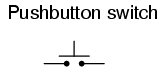
Push button switches are two-position devices actuated with a button that is pressed and released. Most push button switches have an internal spring mechanism returning the button to its “out,” or “unpressed,” position, for momentary operation. Some push button switches will latch alternately on or off with every push of the button. Other push button switches will stay in their “in,” or “pressed,” position until the button is pulled back out. This last type of pushbutton switches usually have a mushroom-shaped button for easy push-pull action.
Selector Switches

Selector switches are actuated with a rotary knob or lever of some sort to select one of two or more positions. Like the toggle switch, selector switches can either rest in any of their positions or contain spring-return mechanisms for momentary operation.
Joystick Switches

A joystick switch is actuated by a lever free to move in more than one axis of motion. One or more of several switch contact mechanisms are actuated depending on which way the lever is pushed, and sometimes by how far it is pushed. The circle-and-dot notation on the switch symbol represents the direction of joystick lever motion required to actuate the contact. Joystick hand switches are commonly used for crane and robot control.
Some switches are specifically designed to be operated by the motion of a machine rather than by the hand of a human operator. These motion-operated switches are commonly called limit switches, because they are often used to limit the motion of a machine by turning off the actuating power to a component if it moves too far.
As with hand switches, limit switches come in several varieties:
Limit Switches
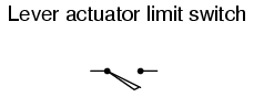
These limit switches closely resemble rugged toggle or selector hand switches fitted with a lever pushed by the machine part. Often, the levers are tipped with a small roller bearing, preventing the lever from being worn off by repeated contact with the machine part.
Proximity Switches
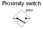
Proximity switches sense the approach of a metallic machine part either by a magnetic or high-frequency electromagnetic field. Simple proximity switches use a permanent magnet to actuate a sealed switch mechanism whenever the machine part gets close (typically 1 inch or less). More complex proximity switches work like a metal detector, energizing a coil of wire with a high-frequency current, and electronically monitoring the magnitude of that current. If a metallic part (not necessarily magnetic) gets close enough to the coil, the current will increase, and trip the monitoring circuit. The symbol shown here for the proximity switch is of the electronic variety, as indicated by the diamond-shaped box surrounding the switch. A non-electronic proximity switch would use the same symbol as the lever-actuated limit switch. Another form of proximity switch is the optical switch, comprised of a light source and photocell. Machine position is detected by either the interruption or reflection of a light beam. Optical switches are also useful in safety applications, where beams of light can be used to detect personnel entry into a dangerous area.
The Different Types of Process Switches
In many industrial processes, it is necessary to monitor various physical quantities with switches. Such switches can be used to sound alarms, indicating that a process variable has exceeded normal parameters, or they can be used to shut down processes or equipment if those variables have reached dangerous or destructive levels. There are many different types of process switches.
Speed Switches

These switches sense the rotary speed of a shaft either by a centrifugal weight mechanism mounted on the shaft, or by some kind of non-contact detection of shaft motion such as optical or magnetic.
Pressure Switches
 Figure 9.8 Pressure switch
Gas or liquid pressure can be used to actuate a switch mechanism if that pressure is applied to a piston, diaphragm, or bellows, which converts pressure to mechanical force.
Temperature Switches

An inexpensive temperature-sensing mechanism is the “bimetallic strip:” a thin strip of two metals, joined back-to-back, each metal having a different rate of thermal expansion. When the strip heats or cools, differing rates of thermal expansion between the two metals causes it to bend. The bending of the strip can then be used to actuate a switch contact mechanism. Other temperature switches use a brass bulb filled with either a liquid or gas, with a tiny tube connecting the bulb to a pressure-sensing switch. As the bulb is heated, the gas or liquid expands, generating a pressure increase which then actuates the switch mechanism.
Liquid Level Switch
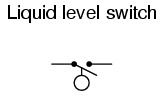
A floating object can be used to actuate a switch mechanism when the liquid level in an tank rises past a certain point. If the liquid is electrically conductive, the liquid itself can be used as a conductor to bridge between two metal probes inserted into the tank at the required depth. The conductivity technique is usually implemented with a special design of relay triggered by a small amount of current through the conductive liquid. In most cases it is impractical and dangerous to switch the full load current of the circuit through a liquid. Level switches can also be designed to detect the level of solid materials such as wood chips, grain, coal, or animal feed in a storage silo, bin, or hopper. A common design for this application is a small paddle wheel, inserted into the bin at the desired height, which is slowly turned by a small electric motor. When the solid material fills the bin to that height, the material prevents the paddle wheel from turning. The torque response of the small motor than trips the switch mechanism. Another design uses a “tuning fork” shaped metal prong, inserted into the bin from the outside at the desired height. The fork is vibrated at its resonant frequency by an electronic circuit and magnet/electromagnet coil assembly. When the bin fills to that height, the solid material dampens the vibration of the fork, the change in vibration amplitude and/or frequency detected by the electronic circuit.
Liquid Flow Switch

Inserted into a pipe, a flow switch will detect any gas or liquid flow rate in excess of a certain threshold, usually with a small paddle or vane which is pushed by the flow. Other flow switches are constructed as differential pressure switches, measuring the pressure drop across a restriction built into the pipe.
Nuclear Level Switch

Another type of level switch, suitable for liquid or solid material detection, is the nuclear switch. Composed of a radioactive source material and a radiation detector, the two are mounted across the diameter of a storage vessel for either solid or liquid material. Any height of material beyond the level of the source/detector arrangement will attenuate the strength of radiation reaching the detector. This decrease in radiation at the detector can be used to trigger a relay mechanism to provide a switch contact for measurement, alarm point, or even control of the vessel level.
Bource and detector are outside of the vessel, with no intrusion at all except the radiation flux itself. The radioactive sources used are fairly weak and pose no immediate health threat to operations or maintenance personnel.
All Switches Have Multiple Applications
As usual, there is more than one way to implement a switch to monitor a physical process or serve as an operator control. There is usually no single “perfect” switch for any application, although some obviously exhibit certain advantages over others. Switches must be intelligently matched to the task for efficient and reliable operation.
- A switch is an electrical device, usually electromechanical, used to control continuity between two points.
- Hand switches are actuated by human touch.
- Limit switches are actuated by machine motion.
- Process switches are actuated by changes in some physical process (temperature, level, flow, etc.).
9.2 Switch Contact Design
A switch can be constructed with any mechanism bringing two conductors into contact with each other in a controlled manner. This can be as simple as allowing two copper wires to touch each other by the motion of a lever, or by directly pushing two metal strips into contact. However, a good switch design must be rugged and reliable, and avoid presenting the operator with the possibility of electric shock. Therefore, industrial switch designs are rarely this crude. The conductive parts in a switch used to make and break the electrical connection are called contacts. Contacts are typically made of silver or silver-cadmium alloy, whose conductive properties are not significantly compromised by surface corrosion or oxidation. Gold contacts exhibit the best corrosion resistance, but are limited in current-carrying capacity and may “cold weld” if brought together with high mechanical force. Whatever the choice of metal, the switch contacts are guided by a mechanism ensuring square and even contact, for maximum reliability and minimum resistance. Contacts such as these can be constructed to handle extremely large amounts of electric current, up to thousands of amps in some cases. The limiting factors for switch contact ampacity are as follows:
- Heat generated by current through metal contacts (while closed).
- Sparking caused when contacts are opened or closed.
- The voltage across open switch contacts (potential of current jumping across the gap).
One major disadvantage of standard switch contacts is the exposure of the contacts to the surrounding atmosphere. In a nice, clean, control-room environment, this is generally not a problem. However, most industrial environments are not this benign. The presence of corrosive chemicals in the air can cause contacts to deteriorate and fail prematurely. Even more troublesome is the possibility of regular contact sparking causing flammable or explosive chemicals to ignite. When such environmental concerns exist, other types of contacts can be considered for small switches. These other types of contacts are sealed from contact with the outside air, and therefore do not suffer the same exposure problems that standard contacts do. A common type of sealed-contact switch is the mercury switch. Mercury is a metallic element, liquid at room temperature. Being a metal, it possesses excellent conductive properties. Being a liquid, it can be brought into contact with metal probes (to close a circuit) inside of a sealed chamber simply by tilting the chamber so that the probes are on the bottom. Many industrial switches use small glass tubes containing mercury which are tilted one way to close the contact, and tilted another way to open. Aside from the problems of tube breakage and spilling mercury (which is a toxic material), and susceptibility to vibration, these devices are an excellent alternative to open-air switch contacts wherever environmental exposure problems are a concern. Here, a mercury switch (often called a tilt switch) is shown in the open position, where the mercury is out of contact with the two metal contacts at the other end of the glass bulb:


Here, the same switch is shown in the closed position. Gravity now holds the liquid mercury in contact with the two metal contacts, providing electrical continuity from one to the other: Mercury switch contacts are impractical to build in large sizes, and so you will typically find such contacts rated at no more than a few amps, and no more than 120 volts. There are exceptions, of course, but these are common limits. Another sealed-contact type of switch is the magnetic reed switch. Like the mercury switch, a reed switch’s contacts are located inside a sealed tube. Unlike the mercury switch which uses liquid metal as the contact medium, the reed switch is simply a pair of very thin, magnetic, metal strips (hence the name “reed”) which are brought into contact with each other by applying a strong magnetic field outside the sealed tube. The source of the magnetic field in this type of switch is usually a permanent magnet, moved closer to or further away from the tube by the actuating mechanism. Due to the small size of the reeds, this type of contact is typically rated at lower currents and voltages than the average mercury switch. However, reed switches typically handle vibration better than mercury contacts, because there is no liquid inside the tube to splash around. It is common to find general-purpose switch contact voltage and current ratings to be greater on any given switch or relay if the electric power being switched is AC instead of DC. The reason for this is the self-extinguishing tendency of an alternating-current arc across an air gap. Because 60 Hz power line current actually stops and reverses direction 120 times per second, there are many opportunities for the ionized air of an arc to lose enough temperature to stop conducting current, to the point where the arc will not re-start on the next voltage peak. DC, on the other hand, is a continuous, uninterrupted flow of electrons which tends to maintain an arc across an air gap much better.
Therefore, switch contacts of any kind incur more wear when switching a given value of direct current than for the same value of alternating current. The problem of switching DC is exaggerated when the load has a significant amount of inductance, as there will be very high voltages generated across the switch’s contacts when the circuit is opened (the inductor doing its best to maintain circuit current at the same magnitude as when the switch was closed). With both AC and DC, contact arcing can be minimized with the addition of a “snubber” circuit (a capacitor and resistor wired in series) in parallel with the contact, like this:
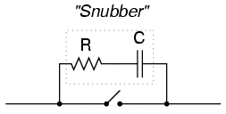
A sudden rise in voltage across the switch contact caused by the contact opening will be tempered by the capacitor’s charging action (the capacitor opposing the increase in voltage by drawing current). The resistor limits the amount of current that the capacitor will discharge through the contact when it closes again. If the resistor were not there, the capacitor might actually make the arcing during contact closure worse than the arcing during contact opening without a capacitor! While this addition to the circuit helps mitigate contact arcing, it is not without disadvantage: a prime consideration is the possibility of a failed (shorted) capacitor/resistor combination providing a path for electrons to flow through the circuit at all times, even when the contact is open and current is not desired. The risk of this failure, and the severity of the resulting consequences must be considered against the increased contact wear (and inevitable contact failure) without the snubber circuit. The use of snubbers in DC switch circuits is nothing new: automobile manufacturers have been doing this for years on engine ignition systems, minimizing the arcing across the switch contact “points” in the distributor with a small capacitor called a condenser. As any mechanic can tell you, the service life of the distributor’s “points” is directly related to how well the condenser is functioning. With all this discussion concerning the reduction of switch contact arcing, one might be led to think that less current is always better for a mechanical switch. This, however, is not necessarily so. It has been found that a small amount of periodic arcing can actually be good for the switch contacts, because it keeps the contact faces free from small amounts of dirt and corrosion. If a mechanical switch contact is operated with too little current, the contacts will tend to accumulate excessive resistance and may fail prematurely! This minimum amount of electric current necessary to keep a mechanical switch contact in good health is called the wetting current. Normally, a switch’s wetting current rating is far below its maximum current rating, and well below its normal operating current load in a properly designed system. However, there are applications where a mechanical switch contact may be required to routinely handle currents below normal wetting current limits (for instance, if a mechanical selector switch needs to open or close a digital logic or analog electronic circuit where the current value is extremely small). In these applications, is it highly recommended that gold-plated switch contacts be specified. Gold is a “noble” metal and does not corrode as other metals will. Such contacts have extremely low wetting current requirements as a result. Normal silver or copper alloy contacts will not provide reliable operation if used in such low-current service!
- The parts of a switch responsible for making and breaking electrical continuity are called the “contacts.” Usually made of corrosion-resistant metal alloy, contacts are made to touch each other by a mechanism which helps maintain proper alignment and spacing.
- Mercury switches use a slug of liquid mercury metal as a moving contact. Sealed in a glass tube, the mercury contact’s spark is sealed from the outside environment, making this type of switch ideally suited for atmospheres potentially harboring explosive vapors.
- Reed switches are another type of sealed-contact device, contact being made by two thin metal “reeds” inside a glass tube, brought together by the influence of an external magnetic field.
- Switch contacts suffer greater duress switching DC than AC. This is primarily due to the self-extinguishing nature of an AC arc.
- A resistor-capacitor network called a “snubber” can be connected in parallel with a switch contact to reduce contact arcing.
- Wetting current is the minimum amount of electric current necessary for a switch contact to carry in order for it to be self-cleaning. Normally this value is far below the switch’s maximum current rating.
9.3 Contact “Normal” State and Make/Break Sequence
Any kind of switch contact can be designed so that the contacts “close” (establish continuity) when actuated, or “open” (interrupt continuity) when actuated. For switches that have a spring-return mechanism in them, the direction that the spring returns it to with no applied force is called the normal position. Therefore, contacts that are open in this position are called normally open and contacts that are closed in this position are called normally closed. For process switches, the normal position, or state, is that which the switch is in when there is no process influence on it. An easy way to figure out the normal condition of a process switch is to consider the state of the switch as it sits on a storage shelf, uninstalled. Here are some examples of “normal” process switch conditions:
- Speed switch: Shaft not turning
- Pressure switch: Zero applied pressure
- Temperature switch: Ambient (room) temperature
- Level switch: Empty tank or bin
- Flow switch: Zero liquid flow
It is important to differentiate between a switch’s “normal” condition and its “normal” use in an operating process. Consider the example of a liquid flow switch that serves as a low-flow alarm in a cooling water system. The normal, or properly-operating, condition of the cooling water system is to have fairly constant coolant flow going through this pipe. If we want the flow switch’s contact to close in the event of a loss of coolant flow (to complete an electric circuit which activates an alarm siren, for example), we would want to use a flow switch with normally-closed rather than normally-open contacts. When there’s adequate flow through the pipe, the switch’s contacts are forced open; when the flow rate drops to an abnormally low level, the contacts return to their normal (closed) state. This is confusing if you think of “normal” as being the regular state of the process, so be sure to always think of a switch’s “normal” state as that which its in as it sits on a shelf. The schematic symbology for switches vary according to the switch’s purpose and actuation. A normally-open switch contact is drawn in such a way as to signify an open connection, ready to close when actuated. Conversely, a normally-closed switch is drawn as a closed connection which will be opened when actuated. Note the following symbols:


Here are a few common switch configurations and their abbreviated designations:


- The normal state of a switch is that where it is unactuated. For process switches, this is the condition its in when sitting on a shelf, uninstalled.
- A switch that is open when unactuated is called normally-open. A switch that is closed when unactuated is called normally-closed. Sometimes the terms “normally-open” and “normally-closed” are abbreviated N.O. and N.C., respectively.
- Multiposition switches can be either break-before-make (most common) or make-before-break.
- The “poles” of a switch refers to the number of moving contacts, while the “throws” of a switch refers to the number of stationary contacts per moving contact.
9.4 Relay Construction
An electric current through a conductor will produce a magnetic field at right angles to the direction of electron flow. If that conductor is wrapped into a coil shape, the magnetic field produced will be oriented along the length of the coil. The greater the current, the greater the strength of the magnetic field, all other factors being equal:

Inductors react against changes in current because of the energy stored in this magnetic field. When we construct a transformer from two inductor coils around a common iron core, we use this field to transfer energy from one coil to the other. However, there are simpler and more direct uses for electromagnetic fields than the applications we’ve seen with inductors and transformers. The magnetic field produced by a coil of current-carrying wire can be used to exert a mechanical force on any magnetic object, just as we can use a permanent magnet to attract magnetic objects, except that this magnet (formed by the coil) can be turned on or off by switching the current on or off through the coil. If we place a magnetic object near such a coil for the purpose of making that object move when we energize the coil with electric current, we have what is called a solenoid. The movable magnetic object is called an armature, and most armatures can be moved with either direct current (DC) or alternating current (AC) energizing the coil. The polarity of the magnetic field is irrelevant for the purpose of attracting an iron armature. Solenoids can be used to electrically open door latches, open or shut valves, move robotic limbs, and even actuate electric switch mechanisms. However, if a solenoid is used to actuate a set of switch contacts, we have a device so useful it deserves its own name: the relay. Relays are extremely useful when we have a need to control a large amount of current and/or voltage with a small electrical signal. The relay coil which produces the magnetic field may only consume fractions of a watt of power, while the contacts closed or opened by that magnetic field may be able to conduct hundreds of times that amount of power to a load.
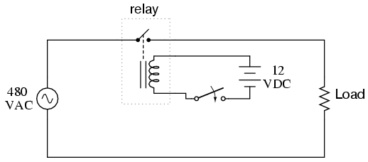
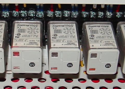
In effect, a relay acts as a binary (on or off) amplifier. Just as with transistors, the relay’s ability to control one electrical signal with another finds application in the construction of logic functions. This topic will be covered in greater detail in another lesson. For now, the relay’s “amplifying” ability will be explored.In the above schematic, the relay’s coil is energized by the low-voltage (12 VDC) source, while the single-pole, single-throw (SPST) contact interrupts the high-voltage (480 VAC) circuit. It is quite likely that the current required to energize the relay coil will be hundreds of times less than the current rating of the contact. Typical relay coil currents are well below 1 amp, while typical contact ratings for industrial relays are at least 10 amps. One relay coil/armature assembly may be used to actuate more than one set of contacts. Those contacts may be normally-open, normally-closed, or any combination of the two. As with switches, the “normal” state of a relay’s contacts is that state when the coil is de-energized, just as you would find the relay sitting on a shelf, not connected to any circuit. Relay contacts may be open-air pads of metal alloy, mercury tubes, or even magnetic reeds, just as with other types of switches. The choice of contacts in a relay depends on the same factors which dictate contact choice in other types of switches. Open-air contacts are the best for high-current applications, but their tendency to corrode and spark may cause problems in some industrial environments. Mercury and reed contacts are sparkless and won’t corrode, but they tend to be limited in current-carrying capacity. Shown here are three small relays (about two inches in height, each), installed on a panel as part of an electrical control system at a municipal water treatment plant: The relay units shown here are called “octal-base,” because they plug into matching sockets, the electrical connections secured via eight metal pins on the relay bottom. The screw terminal connections you see in the photograph where wires connect to the relays are actually part of the socket assembly, into which each relay is plugged. This type of construction facilitates easy removal and replacement of the relay(s) in the event of failure. Aside from the ability to allow a relatively small electrical signal to switch a relatively large electric signal, relays also offer electrical isolation between coil and contact circuits. This means that the coil circuit and contact circuit(s) are electrically insulated from one another. One circuit may be DC and the other AC (such as in the example circuit shown earlier), and/or they may be at completely different voltage levels, across the connections or from connections to ground. While relays are essentially binary devices, either being completely on or completely off, there are operating conditions where their state may be indeterminate, just as with semiconductor logic gates. In order for a relay to positively “pull in” the armature to actuate the contact(s), there must be a certain minimum amount of current through the coil. This minimum amount is called the pull-in current, and it is analogous to the minimum input voltage that a logic gate requires guaranteeing a “high” state (typically 2 Volts for TTL, 3.5 Volts for CMOS). Once the armature is pulled closer to the coil’s center, however, it takes less magnetic field flux (less coil current) to hold it there. Therefore, the coil current must drop below a value significantly lower than the pull-in current before the armature “drops out” to its spring-loaded position and the contacts resume their normal state. This current level is called the drop-out current, and it is analogous to the maximum input voltage that a logic gate input will allow guaranteeing a “low” state (typically 0.8 Volts for TTL, 1.5 Volts for CMOS). The hysteresis, or difference between pull-in and drop-out currents, results in operation that is similar to a Schmitt trigger logic gate. Pull-in and drop-out currents (and voltages) vary widely from relay to relay, and are specified by the manufacturer.
- A solenoid is a device that produces mechanical motion from the energization of an electromagnet coil. The movable portion of a solenoid is called an armature.
- A relay is a solenoid set up to actuate switch contacts when its coil is energized.
- Pull-in current is the minimum amount of coil current needed to actuate a solenoid or relay from its “normal” (de-energized) position.
- Drop-out current is the maximum coil current below which an energized relay will return to its “normal” state.
9.5 Time-delay Relays
What are Time-Delay Relays?
Some relays are constructed with a kind of “shock absorber” mechanism attached to the armature which prevents immediate, full motion when the coil is either energized or de-energized. This addition gives the relay the property of time-delay actuation. Time-delay relays can be constructed to delay armature motion on coil energization, de-energization, or both. Time-delay relay contacts must be specified not only as either normally-open or normally-closed but whether the delay operates in the direction of closing or in the direction of opening. The following is a description of the four basic types of time-delay relay contacts.
Normally-Open, Timed-Closed Contact
First, we have the normally-open, timed-closed (NOTC) contact. This type of contact is normally open when the coil is unpowered (de-energized). The contact is closed by the application of power to the relay coil, but only after the coil has been continuously powered for the specified amount of time. In other words, the direction of the contact’s motion (either to close or to open) is identical to a regular NO contact, but there is a delay in closing direction. Because the delay occurs in the direction of coil energization, this type of contact is alternatively known as a normally-open, on-delay:

The following is a timing diagram of this relay contact’s operation:

Normally-Open, Timed-Open Contact
Next, we have the normally-open, timed-open (NOTO) contact. Like the NOTC contact, this type of contact is normally open when the coil is unpowered (de-energized), and closed by the application of power to the relay coil. However, unlike the NOTC contact, the timing action occurs upon de-energization of the coil rather than upon energization. Because the delay occurs in the direction of coil de-energization, this type of contact is alternatively known as a normally-open, off-delay:
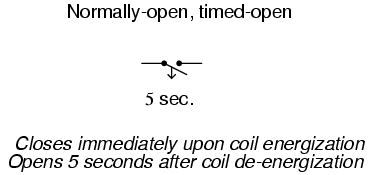
The following is a timing diagram of this relay contact’s operation:

Normally-Closed, Timed-Open Contact
Next, we have the normally-closed, timed-open (NCTO) contact. This type of contact is normally closed when the coil is unpowered (de-energized). The contact is opened with the application of power to the relay coil, but only after the coil has been continuously powered for the specified amount of time. In other words, the direction of the contact’s motion (either to close or to open) is identical to a regular NC contact, but there is a delay in the opening direction. Because the delay occurs in the direction of coil energization, this type of contact is alternatively known as a normally-closed, on-delay:

The following is a timing diagram of this relay contact’s operation:

Normally-Closed, Timed-Closed Contact
Finally, we have the normally-closed, timed-closed (NCTC) contact. Like the NCTO contact, this type of contact is normally closed when the coil is unpowered (de-energized), and opened by the application of power to the relay coil. However, unlike the NCTO contact, the timing action occurs upon de-energization of the coil rather than upon energization. Because the delay occurs in the direction of coil de-energization, this type of contact is alternatively known as a normally-closed, off-delay:

The following is a timing diagram of this relay contact’s operation:

Time-Delay Relays Uses in Industrial Control Logic Circuits
Time-delay relays are very important for use in industrial control logic circuits. Some examples of their use include:
- Flashing light control (time on, time off): two time-delay relays are used in conjunction with one another to provide a constant-frequency on/off pulsing of contacts for sending intermittent power to a lamp.
- Engine auto start control: Engines that are used to power emergency generators are often equipped with “autostart” controls that allow for automatic startup if the main electric power fails. To properly start a large engine, certain auxiliary devices must be started first and allowed some brief time to stabilize (fuel pumps, pre-lubrication oil pumps) before the engine’s starter motor is energized. Time-delay relays help sequence these events for proper start-up of the engine.
- Furnace safety purge control: Before a combustion-type furnace can be safely lit, the air fan must be run for a specified amount of time to “purge” the furnace chamber of any potentially flammable or explosive vapors. A time-delay relay provides the furnace control logic with this necessary time element.
- Motor soft-start delay control: Instead of starting large electric motors by switching full power from a dead stop condition, reduced voltage can be switched for a “softer” start and less inrush current. After a prescribed time delay (provided by a time-delay relay), full power is applied.
- Conveyor belt sequence delay: when multiple conveyor belts are arranged to transport material, the conveyor belts must be started in reverse sequence (the last one first and the first one last) so that material doesn’t get piled on to a stopped or slow-moving conveyor. In order to get large belts up to full speed, some time may be needed (especially if soft-start motor controls are used). For this reason, there is usually a time-delay circuit arranged on each conveyor to give it adequate time to attain full belt speed before the next conveyor belt feeding it is started.
Advanced Timer Features
The older, mechanical time-delay relays used pneumatic dashpots or fluid-filled piston/cylinder arrangements to provide the “shock absorbing” needed to delay the motion of the armature. Newer designs of time-delay relays use electronic circuits with resistor-capacitor (RC) networks to generate a time delay, then energize a normal (instantaneous) electromechanical relay coil with the electronic circuit’s output. The electronic-timer relays are more versatile than the older, mechanical models, and less prone to failure. Many models provide advanced timer features such as “one-shot” (one measured output pulse for every transition of the input from de-energized to energized), “recycle” (repeated on/off output cycles for as long as the input connection is energized) and “watchdog” (changes state if the input signal does not repeatedly cycle on and off).


“Watchdog” Timer Relays
The “watchdog” timer is especially useful for monitoring of computer systems. If a computer is being used to control a critical process, it is usually recommended to have an automatic alarm to detect computer “lockup” (an abnormal halting of program execution due to any number of causes). An easy way to set up such a monitoring system is to have the computer regularly energize and de-energize the coil of a watchdog timer relay (similar to the output of the “recycle” timer). If the computer execution halts for any reason, the signal it outputs to the watchdog relay coil will stop cycling and freeze in one or the other state. A short time thereafter, the watchdog relay will “time out” and signal a problem.
- Time delay relays are built in these four basic modes of contact operation:
- 1: Normally-open, timed-closed. Abbreviated “NOTC”, these relays open immediately upon coil de-energization and close only if the coil is continuously energized for the time duration period. Also called normally-open, on-delay relays.
- 2: Normally-open, timed-open. Abbreviated “NOTO”, these relays close immediately upon coil energization and open after the coil has been de-energized for the time duration period. Also called normally-open, off delay relays.
- 3: Normally-closed, timed-open. Abbreviated “NCTO”, these relays close immediately upon coil de-energization and open only if the coil is continuously energized for the time duration period. Also called normally-closed, on-delay relays.
- 4: Normally-closed, timed-closed. Abbreviated “NCTC”, these relays open immediately upon coil energization and close after the coil has been de-energized for the time duration period. Also called normally-closed, off delay relays.
- One-shot timers provide a single contact pulse of specified duration for each coil energization (transition from coil off to coil on).
- Recycle timers provide a repeating sequence of on-off contact pulses as long as the coil is maintained in an energized state.
- Watchdog timers actuate their contacts only if the coil fails to be continuously sequenced on and off (energized and de-energized) at a minimum frequency.
9.6 “Ladder” Diagrams

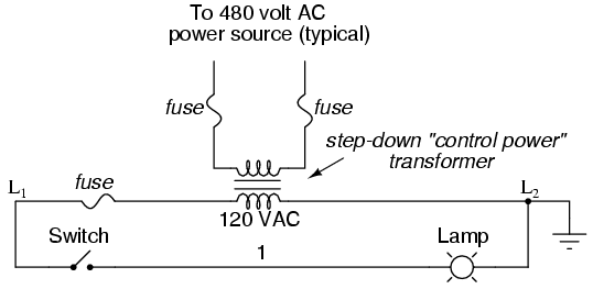

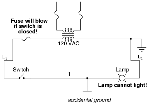
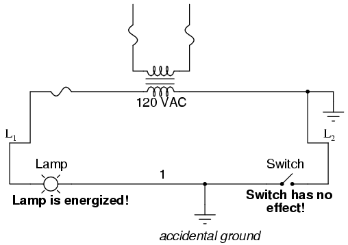
Ladder diagrams are specialized schematics commonly used to document industrial control logic systems. They are called “ladder” diagrams because they resemble a ladder, with two vertical rails (supply power) and as many “rungs” (horizontal lines) as there are control circuits to represent. If we wanted to draw a simple ladder diagram showing a lamp that is controlled by a hand switch, it would look like this: The “L1” and “L2” designations refer to the two poles of a 120 VAC supply unless otherwise noted. L1 is the “hot” conductor, and L2 is the grounded (“neutral”) conductor. These designations have nothing to do with inductors, just to make things confusing. The actual transformer or generator supplying power to this circuit is omitted for simplicity. In reality, the circuit looks something like this:Typically in industrial relay logic circuits, but not always, the operating voltage for the switch contacts and relay coils will be 120 volts AC. Lower voltage AC and even DC systems are sometimes built and documented according to “ladder” diagrams:So long as the switch contacts and relay coils are all adequately rated, it really doesn’t matter what level of voltage is chosen for the system to operate with. Note the number “1” on the wire between the switch and the lamp. In the real world, that wire would be labeled with that number, using heat-shrink or adhesive tags, wherever it was convenient to identify. Wires leading to the switch would be labeled “L1” and “1,” respectively. Wires leading to the lamp would be labeled “1” and “L2,” respectively. These wire numbers make assembly and maintenance very easy. Each conductor has its own unique wire number for the control system that its used in. Wire numbers do not change at any junction or node, even if wire size, color, or length changes going into or out of a connection point. Of course, it is preferable to maintain consistent wire colors, but this is not always practical. What matters is that any one, electrically continuous point in a control circuit possesses the same wire number. Take this circuit section, for example, with wire #25 as a single, electrically continuous point threading to many different devices: In ladder diagrams, the load device (lamp, relay coil, solenoid coil, etc.) is almost always drawn at the right-hand side of the rung. While it doesn’t matter electrically where the relay coil is located within the rung, it does matter which end of the ladder’s power supply is grounded, for reliable operation. Take for instance this circuit: Here, the lamp (load) is located on the right-hand side of the rung, and so is the ground connection for the power source. This is no accident or coincidence; rather, it is a purposeful element of good design practice. Suppose that wire #1 were to accidentally come in contact with ground, the insulation of that wire having been rubbed off so that the bare conductor came in contact with grounded, metal conduit. Our circuit would now function like this:With both sides of the lamp connected to ground, the lamp will be “shorted out” and unable to receive power to light up. If the switch were to close, there would be a short-circuit, immediately blowing the fuse. However, consider what would happen to the circuit with the same fault (wire #1 coming in contact with ground), except this time we’ll swap the positions of switch and fuse (L2 is still grounded):This time the accidental grounding of wire #1 will force power to the lamp while the switch will have no effect. It is much safer to have a system that blows a fuse in the event of a ground fault than to have a system that uncontrollably energizes lamps, relays, or solenoids in the event of the same fault. For this reason, the load(s) must always be located nearest the grounded power conductor in the ladder diagram.

- Ladder diagrams (sometimes called “ladder logic”) are a type of electrical notation and symbology frequently used to illustrate how electromechanical switches and relays are interconnected.
- The two vertical lines are called “rails” and attach to opposite poles of a power supply, usually 120 volts AC. L1 designates the “hot” AC wire and L2 the “neutral” (grounded) conductor.
- Horizontal lines in a ladder diagram are called “rungs,” each one representing a unique parallel circuit branch between the poles of the power supply.
- Typically, wires in control systems are marked with numbers and/or letters for identification. The rule is, all permanently connected (electrically common) points must bear the same label.
9.7 Digital Logic Functions
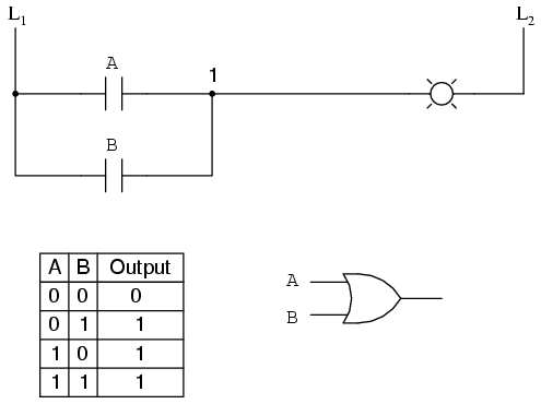
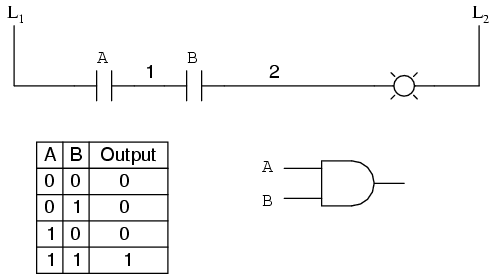
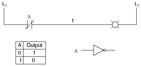
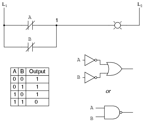
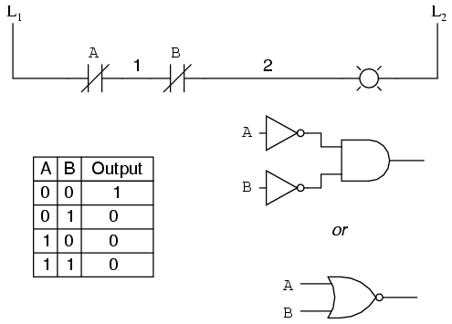
We can construct simple logic functions for our hypothetical lamp circuit, using multiple contacts, and document these circuits quite easily and understandably with additional rungs to our original “ladder.” If we use standard binary notation for the status of the switches and lamp (0 for unactuated or de-energized; 1 for actuated or energized), a truth table can be made to show how the logic works:Now, the lamp will come on if either contact A or contact B is actuated, because all it takes for the lamp to be energized is to have at least one path for current from wire L1 to wire 1. What we have is a simple OR logic function, implemented with nothing more than contacts and a lamp. We can mimic the AND logic function by wiring the two contacts in series instead of parallel:Now, the lamp energizes only if contact A and contact B are simultaneously actuated. A path exists for current from wire L1 to the lamp (wire 2) if and only if both switch contacts are closed. The logical inversion, or NOT, function can be performed on a contact input simply by using a normally-closed contact instead of a normally-open contact:Now, the lamp energizes if the contact is not actuated, and de-energizes when the contact is actuated.If we take our OR function and invert each “input” through the use of normally-closed contacts, we will end up with a NAND function. In a special branch of mathematics known as Boolean algebra, this effect of gate function identity changing with the inversion of input signals is described by DeMorgan’s Theorem, a subject to be explored in more detail in a later chapter.The lamp will be energized if either contact is unactuated. It will go out only if both contacts are actuated simultaneously. Likewise, if we take our AND function and invert each “input” through the use of normally-closed contacts, we will end up with a NOR function:A pattern quickly reveals itself when ladder circuits are compared with their logic gate counterparts:
- Parallel contacts are equivalent to an OR gate.
- Series contacts are equivalent to an AND gate.
- Normally-closed contacts are equivalent to a NOT gate (inverter).
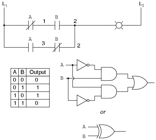
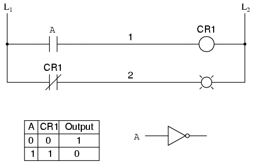
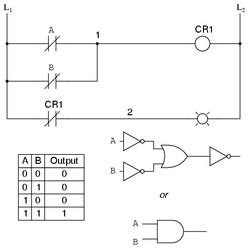
We can build combinational logic functions by grouping contacts in series-parallel arrangements, as well. In the following example, we have an Exclusive-OR function built from a combination of AND, OR, and inverter (NOT) gates:The top rung (NC contact A in series with NO contact B) is the equivalent of the top NOT/AND gate combination. The bottom rung (NO contact A in series with NC contact B) is the equivalent of the bottom NOT/AND gate combination. The parallel connection between the two rungs at wire number 2 forms the equivalent of the OR gate, in allowing either rung 1 or rung 2 to energize the lamp. To make the Exclusive-OR function, we had to use two contacts per input: one for direct input and the other for “inverted” input. The two “A” contacts are physically actuated by the same mechanism, as are the two “B” contacts. The common association between contacts is denoted by the label of the contact. There is no limit to how many contacts per switch can be represented in a ladder diagram, as each new contact on any switch or relay (either normally-open or normally-closed) used in the diagram is simply marked with the same label. Sometimes, multiple contacts on a single switch (or relay) are designated by a compound labels, such as “A-1” and “A-2” instead of two “A” labels. This may be especially useful if you want to specifically designate which set of contacts on each switch or relay is being used for which part of a circuit. For simplicity’s sake, I’ll refrain from such elaborate labeling in this lesson. If you see a common label for multiple contacts, you know those contacts are all actuated by the same mechanism. If we wish to invert the output of any switch-generated logic function, we must use a relay with a normally-closed contact. For instance, if we want to energize a load based on the inverse, or NOT, of a normally-open contact, we could do this:We will call the relay, “control relay 1,” or CR1. When the coil of CR1 (symbolized with the pair of parentheses on the first rung) is energized, the contact on the second rung opens, thus de-energizing the lamp. From switch A to the coil of CR1, the logic function is noninverted. The normally-closed contact actuated by relay coil CR1 provides a logical inverter function to drive the lamp opposite that of the switch’s actuation status. Applying this inversion strategy to one of our inverted-input functions created earlier, such as the OR-to-NAND, we can invert the output with a relay to create a noninverted function:From the switches to the coil of CR1, the logical function is that of a NAND gate. CR1‘s normally-closed contact provides one final inversion to turn the NAND function into an AND function.
- Parallel contacts are logically equivalent to an OR gate.
- Series contacts are logically equivalent to an AND gate.
- Normally closed (N.C.) contacts are logically equivalent to a NOT gate.
- A relay must be used to invert the output of a logic gate function, while simple normally-closed switch contacts are sufficient to represent inverted gate inputs.
9.8 Permissive and Interlock Circuits
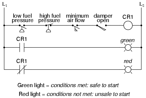

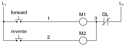

A practical application of switch and relay logic is in control systems where several process conditions have to be met before a piece of equipment is allowed to start. A good example of this is burner control for large combustion furnaces. In order for the burners in a large furnace to be started safely, the control system requests “permission” from several process switches, including high and low fuel pressure, air fan flow check, exhaust stack damper position, access door position, etc. Each process condition is called a permissive, and each permissive switch contact is wired in series, so that if any one of them detects an unsafe condition, the circuit will be opened:If all permissive conditions are met, CR1 will energize and the green lamp will be lit. In real life, more than just a green lamp would be energized: usually, a control relay or fuel valve solenoid would be placed in that rung of the circuit to be energized when all the permissive contacts were “good:” that is, all closed. If any one of the permissive conditions are not met, the series string of switch contacts will be broken, CR2 will de-energize, and the red lamp will light. Note that the high fuel pressure contact is normally-closed. This is because we want the switch contact to open if the fuel pressure gets too high. Since the “normal” condition of any pressure switch is when zero (low) pressure is being applied to it, and we want this switch to open with excessive (high) pressure, we must choose a switch that is closed in its normal state. Another practical application of relay logic is in control systems where we want to ensure two incompatible events cannot occur at the same time. An example of this is in reversible motor control, where two motor contactors are wired to switch polarity (or phase sequence) to an electric motor, and we don’t want the forward and reverse contactors energized simultaneously:When contactor M1 is energized, the 3 phases (A, B, and C) are connected directly to terminals 1, 2, and 3 of the motor, respectively. However, when contactor M2 is energized, phases A and B are reversed, A going to motor terminal 2 and B going to motor terminal 1. This reversal of phase wires results in the motor spinning the opposite direction. Let’s examine the control circuit for these two contactors:Take note of the normally-closed “OL” contact, which is the thermal overload contact activated by the “heater” elements wired in series with each phase of the AC motor. If the heaters get too hot, the contact will change from its normal (closed) state to being open, which will prevent either contactor from energizing. This control system will work fine, so long as no one pushes both buttons at the same time. If someone were to do that, phases A and B would be short-circuited together by virtue of the fact that contactor M1 sends phases A and B straight to the motor and contactor M2 reverses them; phase A would be shorted to phase B and vice versa. Obviously, this is a bad control system design! To prevent this occurrence from happening, we can design the circuit so that the energization of one contactor prevents the energization of the other. This is called interlocking, and it is accomplished through the use of auxiliary contacts on each contactor, as such:Now, when M1 is energized, the normally-closed auxiliary contact on the second rung will be open, thus preventing M2 from being energized, even if the “Reverse” pushbutton is actuated. Likewise, M1‘s energization is prevented when M2 is energized. Note, as well, how additional wire numbers (4 and 5) were added to reflect the wiring changes. It should be noted that this is not the only way to interlock contactors to prevent a short-circuit condition. Some contactors come equipped with the option of a mechanical interlock: a lever joining the armatures of two contactors together so that they are physically prevented from simultaneous closure. For additional safety, electrical interlocks may still be used, and due to the simplicity of the circuit there is no good reason not to employ them in addition to mechanical interlocks.
- Switch contacts installed in a rung of ladder logic designed to interrupt a circuit if certain physical conditions are not met are called permissive contacts, because the system requires permission from these inputs to activate.
- Switch contacts designed to prevent a control system from taking two incompatible actions at once (such as powering an electric motor forward and backward simultaneously) are called interlocks.