
8 TRANSFORMERS
8.1 Step-up and Step-down Transformers
What is Step-up and Step-down Transformers
This is a very useful device, indeed. With it, we can easily multiply or divide voltage and current in AC circuits. Indeed, the transformer has made the long-distance transmission of electric power a practical reality, as AC voltage can be “stepped up” and current “stepped down” for reduced wire resistance power losses along power lines connecting generating stations with loads. At either end (both the generator and at the loads), voltage levels are reduced by transformers for safer operation and less expensive equipment.
A transformer that increases the voltage from primary to secondary (more secondary winding turns than primary winding turns) is called a step-up transformer.
Conversely, a transformer designed to do just the opposite is called a step-down transformer.
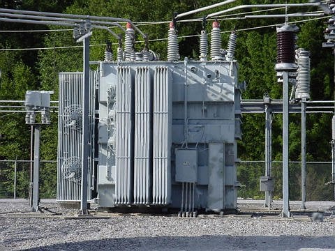
Let’s re-examine a photograph shown in the previous section:
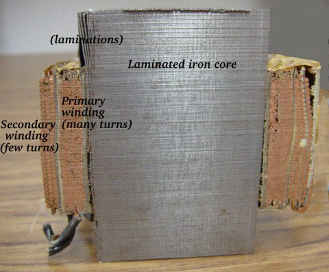
This is a step-down transformer, as evidenced by the high turn count of the primary winding and the low turn count of the secondary. As a step-down unit, this transformer converts high-voltage, low-current power into low-voltage, high-current power. The larger-gauge wire used in the secondary winding is necessary due to the increase in current. The primary winding, which doesn’t have to conduct as much current, may be made of smaller-gauge wire.
Reversibility of Transformer Operation
In case you were wondering, it is possible to operate either of these transformer types backward (powering the secondary winding with an AC source and letting the primary winding power a load) to perform the opposite function: a step-up can function as a step-down and visa-Versa.
However, as we saw in the first section of this chapter, efficient operation of a transformer requires that the individual winding inductances be engineered for specific operating ranges of voltage and current, so if a transformer is to be used “backward” like this it must be employed within the original design parameters of voltage and current for each winding, lest it prove to be inefficient (or lest it be damaged by excessive voltage or current!).
Transformer Construction Labels
Transformers are often constructed in such a way that it is not obvious which wires lead to the primary winding and which lead to the secondary. One convention used in the electric power industry to help alleviate confusion is the use of “H” designations for the higher-voltage winding (the primary winding in a step-down unit; the secondary winding in a step-up) and “X” designations for the lower-voltage winding. Therefore, a simple power transformer will have wires labeled “H1”, “H2”, “X1”, and “X2”. It is usually significant to the numbering of the wires (H1 versus H2, etc.), which we’ll explore a little later in this chapter.
Practical Significance of Step-Up and Step-Down Transformers
The fact that voltage and current get “stepped” in opposite directions (one up, the other down) makes perfect sense when you recall that power is equal to voltage times current, and realize that transformers cannot produce power, only convert it. Any device that could output more power than it took in would violate the Law of Energy Conservation in physics, namely that energy cannot be created or destroyed, only converted. As with the first transformer example we looked at, power transfer efficiency is very good from the primary to the secondary sides of the device.
The practical significance of this is made more apparent when an alternative is considered: before the advent of efficient transformers, voltage/current level conversion could only be achieved through the use of motor/generator sets. A drawing of a motor/generator set reveals the basic principle involved: (Figure below)
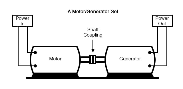
In such a machine, a motor is mechanically coupled to a generator, the generator designed to produce the desired levels of voltage and current at the rotating speed of the motor. While both motors and generators are fairly efficient devices, the use of both in this fashion compounds their inefficiencies so that the overall efficiency is in the range of 90% or less. Furthermore, because motor/generator sets obviously require moving parts, mechanical wear and balance are factors influencing both service life and performance. Transformers, on the other hand, are able to convert levels of AC voltage and current at very high efficiencies with no moving parts, making possible the widespread distribution and use of electric power we take for granted.
In all fairness, it should be noted that motor/generator sets have not necessarily been obsoleted by transformers for all applications. While transformers are clearly superior over motor/generator sets for AC voltage and current level conversion, they cannot convert one frequency of AC power to another, or (by themselves) convert DC to AC or visa-versa. Motor/generator sets can do all these things with relative simplicity, albeit with the limitations of efficiency and mechanical factors already described.
Motor/generator sets also have the unique property of kinetic energy storage: that is, if the motor’s power supply is momentarily interrupted for any reason, its angular momentum (the inertia of that rotating mass) will maintain rotation of the generator for a short duration, thus isolating any loads powered by the generator from “glitches” in the main power system.
Analysis of Step-up and Step-down Transformer Operation
The winding with more inductance have a higher voltage and less current than the other. Since the two inductors are wound around the same core material in the transformer (for the most efficient magnetic coupling between the two), the parameters affecting inductance for the two coils are equal except for the number of turns in each coil. If we take another look at our inductance formula, we see that inductance is proportional to the square of the number of coil turns:
Where,
[latex]L = \text{inductance of coil in Henrys} [/latex]
[latex]N = \text{Number of turns in wire coil (straight wire = 1)}[/latex]
[latex]\mu = \text{Permeability of core materials (absolute, not relative)}[/latex]
[latex]A = \text{Area of coil in square meters}[/latex]
[latex]I = \text{Average of coil in meters}[/latex]
So, it should be apparent that our two inductors should have coil turn ratios of 10:1, because of 10 squared equals 100. This works out to be the same ratio we found between primary and secondary voltages and currents (10:1), so we can say as a rule that the voltage and current transformation ratio is equal to the ratio of winding turns between primary and secondary.
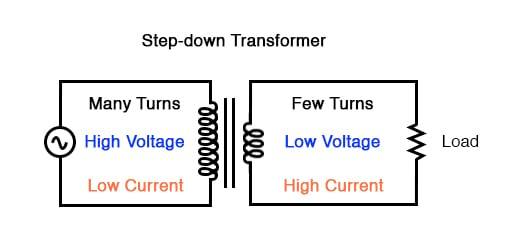
Step-down transformer: (many turns :few turns).
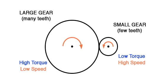
The step-up/step-down effect of coil turn ratios in a transformer is analogous to gear tooth ratios in mechanical gear systems, transforming values of speed and torque in much the same way:
Step-up and step-down transformers for power distribution purposes can be gigantic in proportion to the power transformers previously shown, some units standing as tall as a home. The following photograph shows a substation transformer standing about twelve feet tall:
8.2 Electrical Isolation
There are applications where electrical isolation is needed between two AC circuit without any transformation of voltage or current levels. In these instances, Transformers called isolation transformers having 1:1 transformation ratios are used. A benchtop isolation transformer is shown in the Figure below.

8.3 Phasing
Since transformers are essentially AC devices, we need to be aware of the phase relationships between the primary and secondary circuits. We can plot the waveshapes for the primary and secondary circuits and see the phase relations.

A secondary voltage V(3,5) is in-phase with primary voltage V(2) and stepped down by a factor of ten.
In going from primary, V(2), to secondary, V(3,5), the voltage was stepped down by a factor of ten, and the current was stepped up by a factor of 10. Both current and voltage waveforms are in-phase in going from primary to secondary.

Transformer Conventions
It would appear that both voltage and current for the two transformer windings are in-phase with each other, at least for our resistive load. This is simple enough, but it would be nice to know which way we should connect a transformer in order to ensure the proper phase relationships be kept. After all, a transformer is nothing more than a set of magnetically-linked inductors, and inductors don’t usually come with polarity markings of any kind. If we were to look at an unmarked transformer, we would have no way of knowing which way to hook it up to a circuit to get in-phase (or 180° out-of-phase) voltage and current:

Since this is a practical concern, transformer manufacturers have come up with a sort of polarity marking standard to denote phase relationships. It is called the dot convention, and is nothing more than a dot placed next to each corresponding leg of a transformer winding:

Typically, the transformer will come with some kind of schematic diagram labeling the wire leads for primary and secondary windings. On the diagram will be a pair of dots similar to what is seen above. Sometimes dots will be omitted, but when “H” and “X” labels are used to label transformer winding wires, the subscript numbers are supposed to represent winding polarity. The “1” wires (H1 and X1) represent where the polarity-marking dots would normally be placed.
The similar placement of these dots next to the top ends of the primary and secondary windings tells us that whatever instantaneous voltage polarity is seen across the primary winding will be the same as that across the secondary winding. In other words, the phase shift from primary to secondary will be zero degrees.
On the other hand, if the dots on each winding of the transformer do not match up, the phase shift will be 180° between primary and secondary, like this:

Of course, the dot convention only tells you which end of each winding is which, relative to the other winding(s). If you want to reverse the phase relationship yourself, all you have to do is swap the winding connections like this:

Transformers “step up” or “step down” voltage according to the ratios of primary to secondary wire turns.
[latex]\text{Voltage transmission ratio} = \frac{N_{secondary}}{N_{primary}}[/latex]
[latex]\text{Current transmission ratio} = \frac{N_{primary}}{N_{secondary}}[/latex]
Where,
[latex]N = \text{Number of turns in winding}[/latex]
- A transformer designed to increase the voltage from primary to secondary is called a step-up transformer. A transformer designed to reduce the voltage from primary to secondary is called a step-down transformer.
- The transformation ratio of a transformer will be equal to the square root of its primary to secondary inductance (L) ratio.
[latex]\text{Voltage transmission ratio} = \sqrt{\frac{L_{secondary}}{L_{primary}}}[/latex]
- By being able to transfer power from one circuit to another without the use of interconnecting conductors between the two circuits, transformers provide the useful feature of electrical isolation.
- Transformers designed to provide electrical isolation without stepping voltage and current either up or down are called isolation transformers.
- The phase relationships for voltage and current between primary and secondary circuits of a transformer are direct: ideally, zero phase shift.
- The dot convention is a type of polarity marking for transformer windings showing which end of the winding is which, relative to the other windings.
8.4 Winding Configurations
Transformers with Multiple Secondaries
Transformers are very versatile devices. The basic concept of energy transfer between mutual inductors is useful enough between a single primary and single secondary coil, but transformers don’t have to be made with just two sets of windings. Consider this transformer circuit:

Here, three inductor coils share a common magnetic core, magnetically “coupling” or “linking” them together. The relationship of winding turn ratios and voltage ratios seen with a single pair of mutual inductors still holds true here for multiple pairs of coils.
It is entirely possible to assemble a transformer such as the one above (one primary winding, two secondary windings) in which one secondary winding is a step-down and the other is a step-up. In fact, this design of transformer was quite common in vacuum tube power supply circuits, which were required to supply low voltage for the tubes’ filaments (typically 6 or 12 volts) and high voltage for the tubes’ plates (several hundred volts) from a nominal primary voltage of 110 volts AC.
Not only are voltages and currents of completely different magnitudes possible with such a transformer, but all circuits are electrically isolated from one another.

The transformer in the figure above is intended to provide both high and low voltages necessary in an electronic system using vacuum tubes. Low voltage is required to power the filaments of vacuum tubes, while high voltage is required to create the potential difference between the plate and cathode elements of each tube. One transformer with multiple windings suffices elegantly to provide all the necessary voltage levels from a single 115 V source. The wires for this transformer (15 of them!) are not shown in the photograph, being hidden from view.
If electrical isolation between secondary circuits is not of great importance, a similar effect can be obtained by “tapping” a single secondary winding at multiple points along its length, like the figure below.

Multi-Pole Switch Transformer
A tap is nothing more than a wire connection made at some point on a winding between the very ends. Not surprisingly, the winding turn/voltage magnitude relationship of a normal transformer holds true for all tapped segments of windings. This fact can be exploited to produce a transformer capable of multiple ratios:

Variable Transformer
Carrying the concept of winding taps further, we end up with a “variable transformer,” where a sliding contact is moved along the length of an exposed secondary winding, able to connect with it at any point along its length. The effect is equivalent to having a winding tap at every turn of the winding, and a switch with poles at every tap position:

One consumer application of the variable transformer is in speed controls for model train sets, especially the train sets of the 1950s and 1960s. These transformers were essentially step-down units, the highest voltage obtainable from the secondary winding being substantially less than the primary voltage of 110 to 120 volts AC. The variable-sweep contact provided a simple means of voltage control with little-wasted power, much more efficient than control using a variable resistor!
Moving-slide contacts are too impractical to be used in large industrial power transformer designs, but multi-pole switches and winding taps are common for voltage adjustment. Adjustments need to be made periodically in power systems to accommodate changes in loads over months or years in time, and these switching circuits provide a convenient means. Typically, such “tap switches” are not engineered to handle the full-load current, but must be actuated only when the transformer has been de-energized (no power).
Autotransformer
Seeing as how we can tap any transformer winding to obtain the equivalent of several windings (albeit with loss of electrical isolation between them), it makes sense that it should be possible to forego electrical isolation altogether and build a transformer from a single winding. Indeed this is possible, and the resulting device is called an autotransformer:

The autotransformer depicted above performs a voltage step-up function. A step-down autotransformer would look something like the figure below.

Autotransformers find popular use in applications requiring a slight boost or reduction in voltage to a load. The alternative with a normal (isolated) transformer would be to either have just the right primary/secondary winding ratio made for the job or use a step-down configuration with the secondary winding connected in series-aiding (“boosting”) or series-opposing (“bucking”) fashion. Primary, secondary, and load voltages are given to illustrate how this would work.
Autotransformer Configurations
First, the “boosting” configuration. In the figure below the secondary coil’s polarity is oriented so that its voltage directly adds to the primary voltage.

Next, the “bucking” configuration. In the figure below, the secondary coil’s polarity is oriented so that its voltage directly subtracts from the primary voltage:

The prime advantage of an autotransformer is that the same boosting or bucking function is obtained with only a single winding, making it cheaper and lighter to manufacture than a regular (isolating) transformer having both primary and secondary windings.
Variac Variable Autotransformer
Like regular transformers, autotransformer windings can be tapped to provide variations in ratio. Additionally, they can be made continuously variable with a sliding contact to tap the winding at any point along its length. The latter configuration is popular enough to have earned itself its own name: the Variac. (figure below)

Small variacs for benchtop use are popular pieces of equipment for the electronics experimenter, being able to step household AC voltage down (or sometimes up as well) with a wide, fine range of control by a simple twist of a knob.
- Transformers can be equipped with more than just a single primary and single secondary winding pair. This allows for multiple step-up and/or step-down ratios in the same device.
- Transformer windings can also be “tapped:” that is, intersected at many points to segment a single winding into sections.
- Variable transformers can be made by providing a movable arm that sweeps across the length of a winding, making contact with the winding at any point along its length. The winding, of course, has to be bare (no insulation) in the area where the arm sweeps.
- An autotransformer is a single, tapped inductor coil used to step up or step down voltage like a transformer, except without providing electrical isolation.
- A Variac is a variable autotransformer.
8.5 Three-phase Transformer Circuits
Since three-phase is used so often for power distribution systems, it makes sense that we would need three-phase transformers to be able to step voltages up or down. This is only partially true, as regular single-phase transformers can be ganged together to transform power between two three-phase systems in a variety of configurations, eliminating the requirement for a special three-phase transformer. However, special three-phase transformers are built for those tasks and are able to perform with less material requirement, less size, and less weight than their modular counterparts.
Three-Phase Transformer Windings and Connections
A three-phase transformer is made of three sets of primary and secondary windings, each set wound around one leg of an iron core assembly. Essentially it looks like three single-phase transformers sharing a joined core as in Figure below.

Those sets of primary and secondary windings will be connected in either Δ or Y configurations to form a complete unit. The various combinations of ways that these windings can be connected together it will be the focus of this section.
Whether the winding sets share a common core assembly or each winding pair is a separate transformer, the winding connection options are the same:
Primary – Secondary
- Y – Y
- Y – Δ
- Δ – Y
- Δ – Δ
The reasons for choosing a Y or Δ configuration for transformer winding connections are the same as for any other three-phase application: Y connections provide the opportunity for multiple voltages, while Δ connections enjoy a higher level of reliability (if one winding fails open, the other two can still maintain full line voltages to the load).
Probably the most important aspect of connecting three sets of primary and secondary windings together to form a three-phase transformer bank is paying attention to proper winding phasing (the dots used to denote “polarity” of windings). Remember the proper phase relationships between the phase windings of Δ and Y: (Figure below)

Getting this phasing correct when the windings aren’t shown in regular Y or Δ configuration can be tricky. Let me illustrate, starting with the figure below.

Phase Wiring for “Y-Y” Transformer
Three individual transformers are to be connected together to transform power from one three-phase system to another. First, I’ll show the wiring connections for a Y-Y configuration:

Note in Figure above how all the winding ends marked with dots are connected to their respective phases A, B, and C, while the non-dot ends are connected together to form the centers of each “Y”. Having both primary and secondary winding sets connected in “Y” formations allows for the use of neutral conductors (N1 and N2) in each power system.
Phase Wiring for “Y-Δ” Transformer
Now, we’ll take a look at a Y-Δ configuration:

Note how the secondary windings (bottom set, Figure above) are connected in a chain, the “dot” side of one winding connected to the “non-dot” side of the next, forming the Δ loop. At every connection point between pairs of windings, a connection is made to a line of the second power system (A, B, and C).
Phase Wiring for “Δ-Y” Transformer
Now, let’s examine a Δ-Y system in the figure below.

Such a configuration (Figure above) would allow for the provision of multiple voltages (line-to-line or line-to-neutral) in the second power system, from a source power system having no neutral.
Phase Wiring for “Δ-Δ” Transformer
And finally, we turn to the Δ-Δ configuration:

When there is no need for a neutral conductor in the secondary power system, Δ-Δ connection schemes (Figure above) are preferred because of the inherent reliability of the Δ configuration.
Phase Wiring for “V” or “open-Δ” Transformer
Considering that a Δ configuration can operate satisfactorily missing one winding, some power system designers choose to create a three-phase transformer bank with only two transformers, representing a Δ-Δ configuration with a missing winding in both the primary and secondary sides:

This configuration is called “V” or “Open-Δ.” Of course, each of the two transformers has to be oversized to handle the same amount of power as three in a standard Δ configuration, but the overall size, weight, and cost advantages are often worth it. Bear in mind, however, that with one winding set missing from the Δ shape, this system no longer provides the fault tolerance of a normal Δ-Δ system. If one of the two transformers were to fail, the load voltage and current would definitely be affected.
Real Life Example
The following photograph (figure below) shows a bank of step-up transformers at the Grand Coulee hydroelectric dam in Washington state. Several transformers (green in color) may be seen from this vantage point, and they have grouped in threes: three transformers per hydroelectric generator, wired together in some form of three-phase configuration.
The photograph doesn’t reveal the primary winding connections, but it appears the secondaries are connected in a Y configuration, is that there is only one large high-voltage insulator protruding from each transformer. This suggests the other side of each transformer’s secondary winding is at or near ground potential, which could only be true in a Y system. The building to the left is the powerhouse, where the generators and turbines are housed. On the right, the sloping concrete wall is the downstream face of the dam:

8.6 Practical Considerations – Transformers
Power Capacity
As has already been observed, transformers must be well designed in order to achieve acceptable power coupling, tight voltage regulation, and low exciting current distortion. Also, transformers must be designed to carry the expected values of primary and secondary winding current without any trouble. This means the winding conductors must be made of the proper gauge wire to avoid any heating problems.
Ideal Transformer
An ideal transformer would have perfect coupling (no leakage inductance), perfect voltage regulation, perfectly sinusoidal exciting current, no hysteresis or eddy current losses, and wire thick enough to handle any amount of current. Unfortunately, the ideal transformer would have to be infinitely large and heavy to meet these design goals. Thus, in the business of practical transformer design, compromises must be made.
Additionally, winding conductor insulation is a concern where high voltages are encountered, as they often are in step-up and step-down power distribution transformers. Not only do the windings have to be well insulated from the iron core, but each winding has to be sufficiently insulated from the other in order to maintain electrical isolation between windings.
Transformer Ratings
Respecting these limitations, transformers are rated for certain levels of primary and secondary winding voltage and current, though the current rating is usually derived from a volt-amp (VA) rating assigned to the transformer. For example, take a step-down transformer with a primary voltage rating of 120 volts, a secondary voltage rating of 48 volts, and a VA rating of 1 kVA (1000 VA). The maximum winding currents can be determined as such:kVA (1000 VA). The maximum winding currents can be determined as such:
[latex]\text{Maximum Winding Current}[/latex]
[latex]\tag{8.1} I_{Max} = \frac{S}{E}[/latex]
Sometimes windings will bear current ratings in amps, but this is typically seen on small transformers. Large transformers are almost always rated in terms of winding voltage and VA or kVA
Energy Losses
When transformers transfer power, they do so with a minimum of loss. As it was stated earlier, modern power transformer designs typically exceed 95% efficiency. It is good to know where some of this lost power goes, however, and what causes it to be lost.
There is, of course, power loss due to the resistance of the wire windings. Unless superconducting wires are used, there will always be power dissipated in the form of heat through the resistance of current-carrying conductors. Because transformers require such long lengths of wire, this loss can be a significant factor. Increasing the gauge of the winding wire is one way to minimize this loss, but only with substantial increases in cost, size, and weight.
Eddy-Current Loss
Resistive losses aside, the bulk of transformer power loss is due to magnetic effects in the core. Perhaps the most significant of these “core losses” is an eddy-current loss, which is resistive power dissipation due to the passage of induced currents through the iron of the core. Because iron is a conductor of electricity as well as being an excellent “conductor” of magnetic flux, there will be currents induced in the iron just as there are currents induced in the secondary windings from the alternating magnetic field. These induced currents—as described by the perpendicularity clause of Faraday’s Law —tend to circulate through the cross-section of the core perpendicularly to the primary winding turns. Their circular motion gives them their unusual name: like eddies in a stream of water that circulate rather than move in straight lines.
Iron is a fair conductor of electricity, but not as good as the copper or aluminum from which wire windings are typically made. Consequently, these “eddy currents” must overcome significant electrical resistance as they circulate through the core. In overcoming the resistance offered by the iron, they dissipate power in the form of heat. Hence, we have a source of inefficiency in the transformer that is difficult to eliminate.
Induction Heating
This phenomenon is so pronounced that it is often exploited as a means of heating ferrous (iron-containing) materials. The photograph below shows an “induction heating” unit raising the temperature of a large pipe section. Loops of wire covered by high-temperature insulation encircle the pipe’s circumference, inducing eddy currents within the pipe wall by electromagnetic induction. In order to maximize the eddy current effect, high-frequency alternating current is used rather than power line frequency (60 Hz). The box units at the right of the picture produce the high-frequency AC and control the amount of current in the wires to stabilize the pipe temperature at a pre-determined “set-point.”

Mitigating Eddy Currents
The main strategy in mitigating these wasteful eddy currents in transformer cores is to form the iron core in sheets, each sheet covered with an insulating varnish so that the core is divided up into thin slices. The result is very little width in the core for eddy currents to circulate in:

Laminated cores like the one shown here are standard in almost all low-frequency transformers. Recall from the photograph of the transformer cut in half that the iron core was composed of many thin sheets rather than one solid piece. Eddy current losses increase with frequency, so transformers designed to run on higher-frequency power (such as 400 Hz, used in many military and aircraft applications) must use thinner laminations to keep the losses down to a respectable minimum. This has the undesirable effect of increasing the manufacturing cost of the transformer.
Another, similar technique for minimizing eddy current losses which work better for high-frequency applications is to make the core out of iron powder instead of thin iron sheets. Like the lamination sheets, these granules of iron are individually coated in an electrically insulating material, which makes the core nonconductive except for within the width of each granule. Powdered iron cores are often found in transformers handling radio-frequency currents.
Magnetic Hysteresis
Another “core loss” is that of magnetic hysteresis. All ferromagnetic materials tend to retain some degree of magnetization after exposure to an external magnetic field. This tendency to stay magnetized is called “hysteresis,” and it takes a certain investment in energy to overcome this opposition to change every time the magnetic field produced by the primary winding changes polarity (twice per AC cycle).
This type of loss can be mitigated through good core material selection (choosing a core alloy with low hysteresis, as evidenced by a “thin” B/H hysteresis curve), and designing the core for minimum flux density (large cross-sectional area).
Skin Effect at High Frequencies
Transformer energy losses tend to worsen with increasing frequency. The skin effect within winding conductors reduces the available cross-sectional area for electric charge flow, thereby increasing effective resistance as the frequency goes up and creating more power lost through resistive dissipation. Magnetic core losses are also exaggerated with higher frequencies, eddy currents, and hysteresis effects becoming more severe. For this reason, transformers of significant size are designed to operate efficiently in a limited range of frequencies.
In most power distribution systems where the line frequency is very stable, one would think excessive frequency would never pose a problem. Unfortunately, it does, in the form of harmonics created by nonlinear loads.
As we’ve seen in earlier chapters, nonsinusoidal waveforms are equivalent to additive series of multiple sinusoidal waveforms at different amplitudes and frequencies. In power systems, these other frequencies are whole-number multiples of the fundamental (line) frequency, meaning that they will always be higher, not lower, than the design frequency of the transformer. In significant measure, they can cause severe transformer overheating. Power transformers can be engineered to handle certain levels of power system harmonics, and this capability is sometimes denoted with a “K factor” rating.
Stray Capacitance and Inductance
Aside from power ratings and power losses, transformers often harbor other undesirable limitations that circuit designers must be made aware of. Like their simpler counterparts—inductors—transformers exhibit capacitance due to the insulation dielectric between conductors: from winding to winding, turn to turn (in a single winding), and winding to the core.
Transformer Resonance Frequency
Usually, this capacitance is of no concern in a power application, but small signal applications (especially those of high frequency) may not tolerate this quirk well. Also, the effect of having capacitance along with the windings’ designed inductance gives transformers the ability to resonate at a particular frequency, definitely a design concern in signal applications where the applied frequency may reach this point (usually the resonant frequency of a power transformer is well beyond the frequency of the AC power it was designed to operate on).
Flux Containment
Flux containment (making sure a transformer’s magnetic flux doesn’t escape so as to interfere with another device, and making sure other devices’ magnetic flux is shielded from the transformer core) is another concern shared both by inductors and transformers.
Leakage Inductance
Closely related to the issue of flux containment is leakage inductance. Because leakage inductance is equivalent to an inductance connected in series with the transformer’s winding, it manifests itself as a series impedance with the load. Thus, the more current drawn by the load, the less voltage available at the secondary winding terminals. Usually, good voltage regulation is desired in transformer design, but there are exceptional applications. As was stated before, discharge lighting circuits require a step-up transformer with “loose” (poor) voltage regulation to ensure reduced voltage after the establishment of an arc through the lamp. One way to meet this design criterion is to engineer the transformer with flux leakage paths for magnetic flux to bypass the secondary winding(s). The resulting leakage flux will produce leakage inductance, which will, in turn, produce the poor regulation needed for discharge lighting.
Core Saturation
Transformers are also constrained in their performance by the magnetic flux limitations of the core. For ferromagnetic core transformers, we must be mindful of the saturation limits of the core. Remember that ferromagnetic materials cannot support infinite magnetic flux densities: they tend to “saturate” at a certain level (dictated by the material and core dimensions), meaning that further increases in magnetic field force (mmf) do not result in proportional increases in magnetic field flux (Φ).
When a transformer’s primary winding is overloaded from excessive applied voltage, the core flux may reach saturation levels during peak moments of the AC sine wave cycle. If this happens, the voltage induced in the secondary winding will no longer match the wave-shape as the voltage powering the primary coil. In other words, the overloaded transformer will distort the waveshape from primary to secondary windings, creating harmonics in the secondary winding’s output. As we discussed before, harmonic content in AC power systems typically causes problems.
Peaking Transformers
Special transformers known as peaking transformers exploit this principle to produce brief voltage pulses near the peaks of the source voltage waveform. The core is designed to saturate quickly and sharply, at voltage levels well below peak. This results in a severely cropped sine-wave flux waveform, and secondary voltage pulses only when the flux is changing (below saturation levels):

Operation at Frequencies Lower than Normal
Another cause of abnormal transformer core saturation is operation at frequencies lower than normal. For example, if a power transformer designed to operate at 60 Hz is forced to operate at 50 Hz instead, the flux must reach greater peak levels than before in order to produce the same opposing voltage needed to balance against the source voltage. This is true even if the source voltage is the same as before.

Since instantaneous winding voltage is proportional to the instantaneous magnetic flux’s rate of change in a transformer, a voltage waveform reaching the same peak value, but taking a longer amount of time to complete each half-cycle, demands that the flux maintain the same rate of change as before, but for longer periods of time. Thus, if the flux has to climb at the same rate as before, but for longer periods of time, it will climb to a greater peak value.
Mathematically, this is another example of calculus in action. Because the voltage is proportional to the flux’s rate-of-change, we say that the voltage waveform is the derivative of the flux waveform, “derivative” being that calculus operation defining one mathematical function (waveform) in terms of the rate-of-change of another. If we take the opposite perspective, though, and relate the original waveform to its derivative, we may call the original waveform the integral of the derivative waveform. In this case, the voltage waveform is the derivative of the flux waveform, and the flux waveform is the integral of the voltage waveform.
The integral of any mathematical function is proportional to the area accumulated underneath the curve of that function. Since each half-cycle of the 50 Hz waveform accumulates more area between it and the zero line of the graph than the 60 Hz waveform will—and we know that the magnetic flux is the integral of the voltage—the flux will attain higher values in the Figure below.

Yet another cause of transformer saturation is the presence of DC current in the primary winding. Any amount of DC voltage dropped across the primary winding of a transformer will cause an additional magnetic flux in the core. This additional flux “bias” or “offset” will push the alternating flux waveform closer to saturation in one half-cycle than the other.

For most transformers, core saturation is a very undesirable effect, and it is avoided through good design: engineering the windings and core so that magnetic flux densities remain well below the saturation levels. This ensures that the relationship between mmf and Φ is more linear throughout the flux cycle, which is good because it makes for less distortion in the magnetization current waveform. Also, engineering the core for low flux densities provides a safe margin between the normal flux peaks and the core saturation limits to accommodate occasional, abnormal conditions such as frequency variation and DC offset.
Inrush Current
When a transformer is initially connected to a source of AC voltage, there may be a substantial surge of current through the primary winding called inrush current. This is analogous to the inrush current exhibited by an electric motor that is started up by sudden connection to a power source, although transformer inrush is caused by a different phenomenon.
We know that the rate of change of instantaneous flux in a transformer core is proportional to the instantaneous voltage drop across the primary winding. Or, as stated before, the voltage waveform is the derivative of the flux waveform, and the flux waveform is the integral of the voltage waveform. In a continuously-operating transformer, these two waveforms are phase-shifted by 90°. Since flux (Φ) is proportional to the magnetomotive force (mmf) in the core, and the mmf is proportional to winding current, the current waveform will be in-phase with the flux waveform, and both will be lagging the voltage waveform by 90°:

Let us suppose that the primary winding of a transformer is suddenly connected to an AC voltage source at the exact moment in time when the instantaneous voltage is at its positive peak value. In order for the transformer to create an opposing voltage drop to balance against this applied source voltage, a magnetic flux of rapidly increasing value must be generated. The result is that winding current increases rapidly, but actually no more rapidly than under normal conditions:

Both core flux and coil current start from zero and build up to the same peak values experienced during continuous operation. Thus, there is no “surge” or “inrush” or current in this scenario.
Alternatively, let us consider what happens if the transformer’s connection to the AC voltage source occurs at the exact moment in time when the instantaneous voltage is at zero. During continuous operation (when the transformer has been powered for quite some time), this is the point in time where both flux and winding current are at their negative peaks, experiencing zero rate-of-change (dΦ/dt = 0 and di/dt = 0). As the voltage builds to its positive peak, the flux and current waveforms build to their maximum positive rates-of-change, and on upward to their positive peaks as the voltage descends to a level of zero:

A significant difference exists, however, between continuous-mode operation and the sudden starting condition assumed in this scenario: during continuous operation, the flux and current levels were at their negative peaks when voltage was at its zero points; in a transformer that has been sitting idle, however, both magnetic flux and winding current should start at zero.
When the magnetic flux increases in response to a rising voltage, it will increase from zero upward, not from a previously negative (magnetized) condition as we would normally have in a transformer that’s been powered for a while. Thus, in a transformer that’s just “starting,” the flux will reach approximately twice its normal peak magnitude as it “integrates” the area under the voltage waveform’s first half-cycle:

Starting at e=0 V, Φ starts at initial condition Φ=0, increasing to twice the normal value, assuming it doesn’t saturate the core.
In an ideal transformer, the magnetizing current would rise to approximately twice its normal peak value as well, generating the necessary mmf to create this higher-than-normal flux. However, most transformers aren’t designed with enough of a margin between normal flux peaks and the saturation limits to avoid saturating in a condition like this, and so the core will almost certainly saturate during this first half-cycle of voltage. During saturation, disproportionate amounts of mmf are needed to generate magnetic flux. This means that winding current, which creates the mmf to cause a flux in the core, will disproportionately rise to a value easily exceeding twice its normal peak:

This is the mechanism causing inrush current in a transformer’s primary winding when connected to an AC voltage source. As you can see, the magnitude of the inrush current strongly depends on the exact time that electrical connection to the source is made. If the transformer happens to have some residual magnetism in its core at the moment of connection to the source, the inrush could be even more severe. Because of this, transformer overcurrent protection devices are usually of the “slow-acting” variety, so as to tolerate current surges such as this without opening the circuit.
Heat and Noise
In addition to unwanted electrical effects, transformers may also exhibit undesirable physical effects, the most notable being the production of heat and noise. Noise is primarily a nuisance effect, but heat is a potentially serious problem because winding insulation will be damaged if allowed to overheat. Heating may be minimized by good design, ensuring that the core does not approach saturation levels, that eddy currents are minimized, and that the windings are not overloaded or operated too close to maximum ampacity.
Large power transformers have their core and windings submerged in an oil bath to transfer heat and muffle noise, and also to displace moisture which would otherwise compromise the integrity of the winding insulation. Heat-dissipating “radiator” tubes on the outside of the transformer case provide a convective oil flow path to transfer heat from the transformer’s core to ambient air:

Oil-less, or “dry,” transformers are often rated in terms of maximum operating temperature “rise” (temperature increase beyond ambient) according to a letter-class system: A, B, F, or H. These letter codes are arranged in order of lowest heat tolerance to highest:
- Class A: No more than 55° Celsius winding temperature rise, at 40° Celsius (maximum) ambient air temperature.
- Class B: No more than 80° Celsius winding temperature rise, at 40° Celsius (maximum)ambient air temperature.
- Class F: No more than 115° Celsius winding temperature rise, at 40° Celsius (maximum)ambient air temperature.
- Class H: No more than 150° Celsius winding temperature rise, at 40° Celsius (maximum)ambient air temperature.
Audible noise is an effect primarily originating from the phenomenon of magnetostriction: the slight change of length exhibited by a ferromagnetic object when magnetized. The familiar “hum” heard around large power transformers is the sound of the iron core expanding and contracting at 120 Hz (twice the system frequency, which is 60 Hz in the United States)—one cycle of core contraction and expansion for every peak of the magnetic flux waveform—plus noise created by mechanical forces between primary and secondary windings. Again, maintaining low magnetic flux levels in the core is the key to minimizing this effect, which explains why ferroresonant transformers—which must operate in saturation for a large portion of the current waveform—operate both hot and noisy.
Losses due to Winding Magnetic Forces
Another noise-producing phenomenon in power transformers is the physical reaction force between primary and secondary windings when heavily loaded. If the secondary winding is open-circuited, there will be no current through it, and consequently, no magneto-motive force (mmf) produced by it. However, when the secondary is “loaded” (currently supplied to a load), the winding generates an mmf, which becomes counteracted by a “reflected” mmf in the primary winding to prevent core flux levels from changing. These opposing mmf’s generated between primary and secondary windings as a result of secondary (load) current produce a repulsive, physical force between the windings which will tend to make them vibrate. Transformer designers have to consider these physical forces in the construction of the winding coils, to ensure there is adequate mechanical support to handle the stresses. Under heavy load (high current) conditions, though, these stresses may be great enough to cause audible noise to emanate from the transformer.
- Power transformers are limited in the amount of power they can transfer from primary to secondary winding(s). Large units are typically rated in VA (volt-amps) or kVA (kilo volt-amps).
- Resistance in transformer windings contributes to inefficiency, as current will dissipate heat, wasting energy.
- Magnetic effects in a transformer’s iron core also contribute to inefficiency. Among the effects are eddy currents (circulating induction currents in the iron core) and hysteresis (power lost due to overcoming the tendency of iron to magnetize in a particular direction).
- Increased frequency results in increased power losses within a power transformer. The presence of harmonics in a power system is a source of frequencies significantly higher than normal, which may cause overheating in large transformers.
- Both transformers and inductors harbor certain unavoidable amounts of capacitance due to wire insulation (dielectric) separating winding turns from the iron core and from each other. This capacitance can be significant enough to give the transformer a natural resonant frequency, which can be problematic in signal applications.
- Leakage inductance is caused by magnetic flux not being 100% coupled between windings in a transformer. Any flux not involved with transferring energy from one winding to another will store and release energy, which is how (self-) inductance works. Leakage inductance tends to worsen a transformer’s voltage regulation (secondary voltage “sags” more for a given amount of load current).
- Magnetic saturation of a transformer core may be caused by excessive primary voltage, operation at too low of a frequency, and/or by the presence of a DC current in any of the windings. Saturation may be minimized or avoided by conservative design, which provides an adequate margin of safety between peak magnetic flux density values and the saturation limits of the core.
- Transformers often experience significant inrush currents when initially connected to an AC voltage source. Inrush current is most severe when the connection to the AC source is made at the moment instantaneous source voltage is zero.
- Noise is a common phenomenon exhibited by transformers—especially power transformers—and is primarily caused by magnetostriction of the core. Physical forces causing winding vibration may also generate noise under conditions of heavy (high current) secondary winding load.