
10 MOTOR CIRCUITS AND CONTROL
10.1 Motor Control Circuits
The interlock contacts installed in the previous section’s motor control circuit work fine, but the motor will run only as long as each push button switch is held down. If we wanted to keep the motor running even after the operator takes his or her hand off the control switch(es), we could change the circuit in a couple of different ways: we could replace the push button switches with toggle switches, or we could add some more relay logic to “latch” the control circuit with a single, momentary actuation of either switch. Let’s see how the second approach is implemented since it is commonly used in industry:
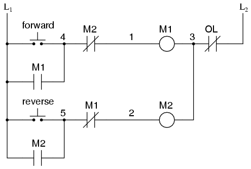
When the “Forward” pushbutton is actuated, M1 will energize, closing the normally-open auxiliary contact in parallel with that switch. When the pushbutton is released, the closed M1 auxiliary contact will maintain current to the coil of M1, thus latching the “Forward” circuit in the “on” state. The same sort of thing will happen when the “Reverse” pushbutton is pressed. These parallel auxiliary contacts are sometimes referred to as seal-in contacts, the word “seal” meaning essentially the same thing as the word latch. However, this creates a new problem: how to stop the motor! As the circuit exists right now, the motor will run either forward or backward once the corresponding pushbutton switch is pressed and will continue to run as long as there is power. To stop either circuit (forward or backward), we require some means for the operator to interrupt power to the motor contactors. We’ll call this new switch, Stop:
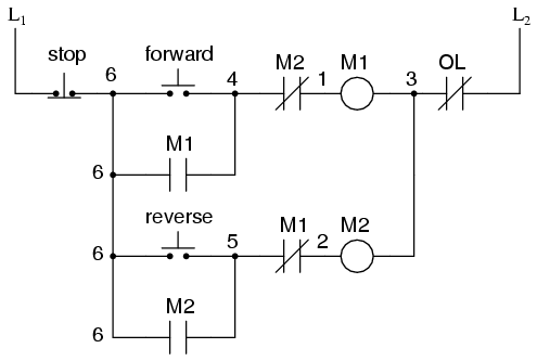
Now, if either forward or reverse circuits are latched, they may be “unlatched” by momentarily pressing the “Stop” pushbutton, which will open either forward or reverse circuit, de-energizing the energized contactor, and returning the seal-in contact to its normal (open) state. The “Stop” switch, having normally-closed contacts, will conduct power to either forward or reverse circuits when released. So far, so good. Let’s consider another practical aspect of our motor control scheme before we quit adding to it. If our hypothetical motor turned a mechanical load with a lot of momentum, such as a large air fan, the motor might continue to coast for a substantial amount of time after the stop button had been pressed. This could be problematic if an operator were to try to reverse the motor direction without waiting for the fan to stop turning. If the fan was still coasting forward and the “Reverse” pushbutton was pressed, the motor would struggle to overcome that inertia of the large fan as it tried to begin turning in reverse, drawing excessive current and potentially reducing the life of the motor, drive mechanisms, and fan. What we might like to have is some kind of a time-delay function in this motor control system to prevent such a premature startup from happening. Let’s begin by adding a couple of time-delay relay coils, one in parallel with each motor contactor coil. If we use contacts that delay returning to their normal state, these relays will provide us a “memory” of which direction the motor was last powered to turn. What we want each time-delay contact to do is to open the starting-switch leg of the opposite rotation circuit for several seconds, while the fan coasts to a halt.
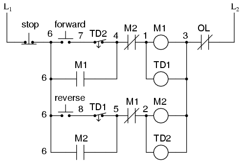
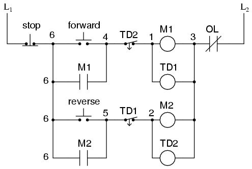
If the motor has been running in the forward direction, both M1 and TD1 will have been energized. This being the case, the normally-closed, timed-closed contact of TD1 between wires 8 and 5 will have immediately opened the moment TD1 was energized. When the stop button is pressed, contact TD1 waits for the specified amount of time before returning to its normally-closed state, thus holding the reverse pushbutton circuit open for the duration so M2 can’t be energized. When TD1 times out, the contact will close and the circuit will allow M2 to be energized if the reverse pushbutton is pressed. In like manner, TD2 will prevent the “Forward” pushbutton from energizing M1 until the prescribed time delay after M2 (and TD2) have been de-energized. The careful observer will notice that the time-interlocking functions of TD1 and TD2 render the M1 and M2 interlocking contacts redundant. We can get rid of auxiliary contacts M1 and M2 for interlocks and just use TD1 and TD2‘s contacts, since they immediately open when their respective relay coils are energized, thus “locking out” one contactor if the other is energized. Each time delay relay will serve a dual purpose: preventing the other contactor from energizing while the motor is running and preventing the same contactor from energizing until a prescribed time after motor shutdown. The resulting circuit has the advantage of being simpler than the previous example:
- Motor contactor (or “starter”) coils are typically designated by the letter “M” in ladder logic diagrams.
- Continuous motor operation with a momentary “start” switch is possible if a normally-open “seal-in” contact from the contactor is connected in parallel with the start switch so that once the contactor is energized it maintains power to itself and keeps itself “latched” on.
- Time delay relays are commonly used in large motor control circuits to prevent the motor from being started (or reversed) until a certain amount of time has elapsed from an event.
10.2 Contactors
All About Contactors
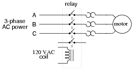
When a relay is used to switch a large amount of electrical power through its contacts, it is designated by a special name: contactor. Contactors typically have multiple contacts, and those contacts are usually (but not always) normally-open, so that power to the load is shut off when the coil is de-energized. Perhaps the most common industrial use for contactors is the control of electric motors.The top three contacts switch the respective phases of the incoming 3-phase AC power, typically at least 480 Volts for motors 1 horsepower or greater. The lowest contact is an “auxiliary” contact which has a current rating much lower than that of the large motor power contacts, but is actuated by the same armature as the power contacts. The auxiliary contact is often used in a relay logic circuit, or for some other part of the motor control scheme, typically switching 120 Volt AC power instead of the motor voltage. One contactor may have several auxiliary contacts, either normally-open or normally-closed if required.
The three “opposed-question-mark” shaped devices in series with each phase going to the motor are called overload heaters. Each “heater” element is a low-resistance strip of metal intended to heat up as the motor draws current. If the temperature of any of these heater elements reaches a critical point (equivalent to a moderate overloading of the motor), a normally-closed switch contact (not shown in the diagram) will spring open. This normally-closed contact is usually connected in series with the relay coil, so that when it opens the relay will automatically de-energize, thereby shutting off power to the motor. We will see more of this overload protection wiring in the next chapter. Overload heaters are intended to provide overcurrent protection for large electric motors, unlike circuit breakers and fuses which serve the primary purpose of providing overcurrent protection for power conductors. Overload heater function is often misunderstood. They are not fuses; that is, it is not their function to burn open and directly break the circuit as a fuse is designed to do. Rather, overload heaters are designed to thermally mimic the heating characteristic of the particular electric motor to be protected. All motors have thermal characteristics, including the amount of heat energy generated by resistive dissipation (I2R), the thermal transfer characteristics of heat “conducted” to the cooling medium through the metal frame of the motor, the physical mass and specific heat of the materials constituting the motor, etc. These characteristics are mimicked by the overload heater on a miniature scale: when the motor heats up toward its critical temperature, so will the heater toward its critical temperature, ideally at the same rate and approach curve. Thus, the overload contact, in sensing heater temperature with a thermomechanical mechanism, will sense an analog of the real motor. If the overload contact trips due to excessive heater temperature, it will be an indication that the real motor has reached its critical temperature (or, would have done so in a short while). After tripping, the heaters are supposed to cool down at the same rate and approach curve as the real motor, so that they indicate an accurate proportion of the motor’s thermal condition, and will not allow power to be re-applied until the motor is truly ready for start-up again.
Three-Phase Electric Motor Contactor
Shown here is a contactor for a three-phase electric motor, installed on a panel as part of an electrical control system at a municipal water treatment plant:
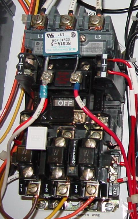
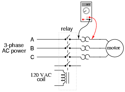
Three-phase, 480 volt AC power comes into the three normally-open contacts at the top of the contactor via screw terminals labeled “L1,” “L2,” and “L3” (The “L2” terminal is hidden behind a square-shaped “snubber” circuit connected across the contactor’s coil terminals). Power to the motor exits the overload heater assembly at the bottom of this device via screw terminals labeled “T1,” “T2,” and “T3.” The overload heater units themselves are black, square-shaped blocks with the label “W34,” indicating a particular thermal response for a certain horsepower and temperature rating of the electric motor. If an electric motor of differing power and/or temperature ratings were to be substituted for the one presently in service, the overload heater units would have to be replaced with units having a thermal response suitable for the new motor. The motor manufacturer can provide information on the appropriate heater units to use. A white push button located between the “T1” and “T2” line heaters serves as a way to manually reset the normally-closed switch contact back to its normal state after having been tripped by excessive heater temperature. Wire connections to the “overload” switch contact may be seen at the lower-right of the photograph, near a label reading “NC” (normally-closed). On this particular overload unit, a small “window” with the label “Tripped” indicates a tripped condition by means of a colored flag. In this photograph, there is no “tripped” condition, and the indicator appears clear. As a footnote, heater elements may be used as a crude current shunt resistor for determining whether or not a motor is drawing current when the contactor is closed. There may be times when you’re working on a motor control circuit, where the contactor is located far away from the motor itself. How do you know if the motor is consuming power when the contactor coil is energized and the armature has been pulled in? If the motor’s windings are burnt open, you could be sending voltage to the motor through the contactor contacts, but still, have zero current, and thus no motion from the motor shaft. If a clamp-on ammeter isn’t available to measure line current, you can take your multimeter and measure millivoltage across each heater element: if the current is zero, the voltage across the heater will be zero (unless the heater element itself is open, in which case the voltage across it will be large); if there is current going to the motor through that phase of the contactor, you will read a definite millivoltage across that heater. This is an especially useful trick to use for troubleshooting 3-phase AC motors, to see if one phase winding is burnt open or disconnected, which will result in a rapidly destructive condition known as “single-phasing.” If one of the lines carrying power to the motor is open, it will not have any current through it (as indicated by a 0.00 mV reading across its heater), although the other two lines will (as indicated by small amounts of voltage dropped across the respective heaters).
- A contactor is a large relay, usually used to switch current to an electric motor or another high-power load.
- Large electric motors can be protected from overcurrent damage through the use of overload heaters and overload contacts. If the series-connected heaters get too hot from excessive current, the normally-closed overload contact will open, de-energizing the contactor sending power to the motor.