
5 MOTOR CHARACTERISTICS
5.1 Introduction
After the introduction of the DC electrical distribution system by Edison in the United States, a gradual transition to the more economical AC system commenced. The lighting worked as well on AC as on DC. Transmission of electrical energy covered longer distances at a lower loss with alternating current. However, motors were a problem with alternating current. Initially, AC motors were constructed like DC motors, but numerous problems were encountered due to changing magnetic fields.
Charles P. Steinmetz contributed to solving these problems with his investigation of hysteresis losses in iron armatures. Nikola Tesla envisioned an entirely new type of motor when he visualized a spinning turbine, not spun by water or steam, but by a rotating magnetic field. His new type of motor, the AC induction motor, is the workhorse of the industry to this day. Its ruggedness and simplicity make for long life, high reliability, and low maintenance. Yet small brushed AC motors, similar to the DC variety, persist in small appliances along with small Tesla induction motors. Above one horsepower (750 W), the Tesla motor reigns supreme.
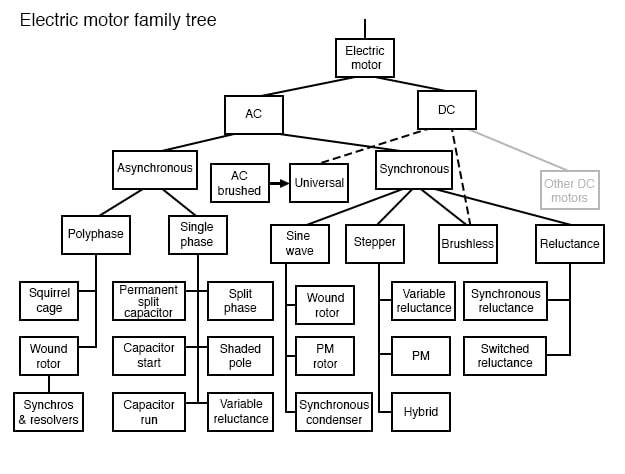
Modern solid-state electronic circuits drive brushless DC motors with AC waveforms generated from a DC source. The brushless DC motor, actually an AC motor, is replacing the conventional brushed DC motor in many applications. And, the stepper motor, a digital version of the motor, is driven by alternating current square waves, again, generated by solid-state circuitry. The figure above shows the family tree of the AC motors described in this chapter.
Cruise ships and other large vessels replace reduction geared driveshafts with large multi-megawatt generators and motors. Such has been the case with diesel-electric locomotives on a smaller scale for many years.

At the system level, (Figure above) a motor takes in electrical energy in terms of a potential difference and a current flow, converting it to mechanical work. Unfortunately, electric motors are not 100% efficient. Some of the electric energy is lost to heat, another form of energy, due to I2R losses (also called copper losses) in the motor windings. The heat is an undesired byproduct of this conversion. It must be removed from the motor and may adversely affect longevity. Thus, one goal is to maximize motor efficiency, reducing heat loss. AC motors also have some losses not encountered by DC motors: hysteresis and eddy currents.
5.2 Tesla Polyphase Induction Motors
Most AC motors are induction motors. Induction motors are favored due to their ruggedness and simplicity. In fact, 90% of industrial motors are induction motors.
Nikola Tesla conceived the basic principles of the polyphase induction motor in 1883 and had a half horsepower (400 watts) model by 1888. Tesla sold the manufacturing rights to George Westinghouse for $65,000.Most large ( > 1 hp or 1 kW) industrial motors are polyphase induction motors. By polyphase, we mean that the stator contains multiple distinct windings per motor pole, driven by corresponding time-shifted sine waves. In practice, this is two or three phases. Large industrial motors are 3-phase. While we include numerous illustrations of two-phase motors for simplicity, we must emphasize that nearly all polyphase motors are three-phase. By induction motor, we mean that the stator windings induce a current flow in the rotor conductors, like a transformer, unlike a brushed DC commutator motor.
AC Induction Motor Construction
An induction motor is composed of a rotor, known as an armature, and a stator containing windings connected to a polyphase energy source as shown in the figure below. The simple 2-phase induction motor below is similar to the 1/2 horsepower motor which Nikola Tesla introduced in 1888.
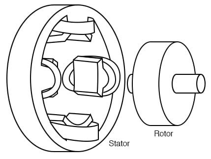
The stator in the figure above is wound with pairs of coils corresponding to the phases of electrical energy available. The 2-phase induction motor stator above has 2-pairs of coils, one pair for each of the two phases of AC. The individual coils of a pair are connected in series and correspond to the opposite poles of an electromagnet. That is, one coil corresponds to an N-pole, the other to an S-pole until the phase of AC changes polarity. The other pair of coils is oriented 90° in space to the first pair. This pair of coils is connected to AC shifted in time by 90° in the case of a 2-phase motor. In Tesla’s time, the source of the two phases of AC was a 2-phase alternator. The stator in the figure above has salient, obvious protruding poles, as used on Tesla’s early induction motor. This design is used to this day for sub-fractional horsepower motors (<50 watts). However, for larger motors, less torque pulsation and higher efficiency results if the coils are embedded into slots cut into the stator laminations (figure below).
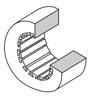
The stator laminations are thin insulated rings with slots punched from sheets of electrical grade steel. A stack of these is secured by end screws, which may also hold the end housings.
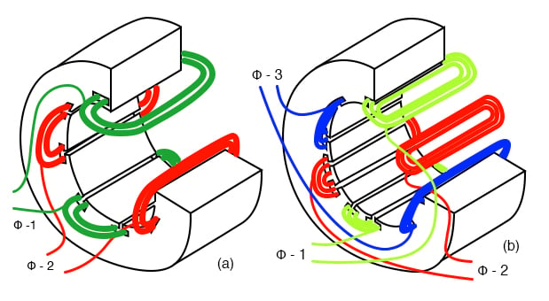
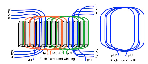
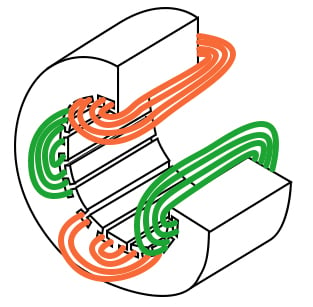
In the figure above, the windings for both a two-phase motor and a three-phase motor have been installed in the stator slots. The coils are wound on an external fixture, then worked into the slots. Insulation wedged between the coil periphery and the slot protects against abrasion.Actual stator windings are more complex than the single windings per pole in the figure above. Comparing the 2-φ motor to Tesla’s 2-φ motor with salient poles, the number of coils is the same. In actual large motors, a pole winding is divided into identical coils inserted into many smaller slots than above. This group is called a phase belt (see the figure below). The distributed coils of the phase belt cancel some of the odd harmonics, producing a more sinusoidal magnetic field distribution across the pole. This is shown in the synchronous motor section. The slots at the edge of the pole may have fewer turns than the other slots. Edge slots may contain windings from two phases. That is, the phase belts overlap.
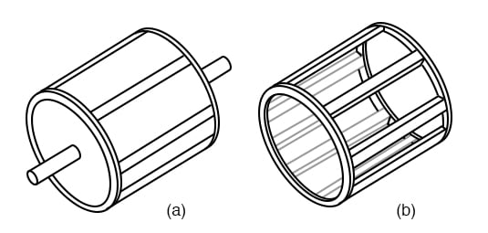
The key to the popularity of the AC induction motor is its simplicity as evidenced by the simple rotor (figure below). The rotor consists of a shaft, a steel laminated rotor, and an embedded copper or aluminum squirrel cage, shown at (b) removed from the rotor. As compared to a DC motor armature, there is no commutator. This eliminates the brushes, arcing, sparking, graphite dust, brush adjustment and replacement, and re-machining of the commutator.
The squirrel cage conductors may be skewed, twisted, with respect to the shaft. The misalignment with the stator slots reduces torque pulsations.Both rotor and stator cores are composed of a stack of insulated laminations. The laminations are coated with insulating oxide or varnish to minimize eddy current losses. The alloy used in the laminations is selected for low hysteresis losses.
Theory of Operation of Induction Motors
A short explanation of operation is that the stator creates a rotating magnetic field which drags the rotor around.The theory of operation of induction motors is based on a rotating magnetic field. One way of creating a rotating magnetic field is to rotate a permanent magnet. If the moving magnetic lines of flux cut a conductive disk, it will follow the motion of the magnet. The lines of flux cutting the conductor will induce a voltage, and consequent current flow, in the conductive disk. This current flow creates an electromagnet whose polarity opposes the motion of the permanent magnet– Lenz’s Law. The polarity of the electromagnet is such that it pulls against the permanent magnet. The disk follows with a little less speed than the permanent magnet.
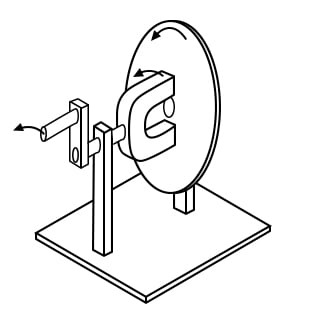
Rotating magnetic field produces torque in conductive disk
The torque developed by the disk is proportional to the number of flux lines cutting the disk and the rate at which it cuts the disk. If the disk were to spin at the same rate as the permanent magnet, there would be no flux cutting the disk, no induced current flow, no electromagnet field, no torque. Thus, the disk speed will always fall behind that of the rotating permanent magnet, so that lines of flux cut the disk induce a current, create an electromagnetic field in the disk, which follows the permanent magnet. If a load is applied to the disk, slowing it, more torque will be developed as more lines of flux cut the disk. Torque is proportional to slip, the degree to which the disk falls behind the rotating magnet. More slip corresponds to more flux cutting the conductive disk, developing more torque.An analog automotive eddy-current speedometer is based on the principle illustrated above. With the disk restrained by a spring, disk and needle deflection is proportional to the magnet rotation rate.A rotating magnetic field is created by two coils placed at right angles to each other, driven by currents which are 90° out of phase. This should not be surprising if you are familiar with oscilloscope Lissajous patterns.
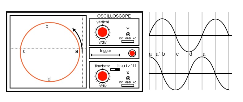
Out of phase (90°), sine waves produce circular Lissajous patternIn the figure above, a circular Lissajous is produced by driving the horizontal and vertical oscilloscope inputs with 90° out of phase sine waves. Starting at (a) with maximum “X” and minimum “Y” deflection, the trace moves up and left toward (b). Between (a) and (b) the two waveforms are equal to 0.707 Vpk at 45°. This point (0.707, 0.707) falls on the radius of the circle between (a) and (b) The trace moves to (b) with minimum “X” and maximum “Y” deflection. With maximum negative “X” and minimum “Y” deflection, the trace moves to (c). Then with minimum “X” and maximum negative “Y”, it moves to (d), and on back to (a), completing one cycle.
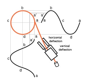
The figure shows the two 90° phase-shifted sine waves applied to oscilloscope deflection plates which are at right angles in space. The combination of 90° phased sine waves and right angle deflection, results in a two-dimensional pattern– a circle. This circle is traced out by a counterclockwise-rotating electron beam.
Full Motor Speed and Synchronous Motor Speed
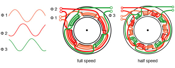
The rotation rate of a stator rotating magnetic field is related to the number of pole pairs per stator phase. The “full speed” figure below has a total of six poles or three pole-pairs and three phases. However, there is but one pole pair per phase. The magnetic field will rotate once per sine wave cycle. In the case of 60 Hz power, the field rotates at 60 times per second or 3600 revolutions per minute (rpm). For 50 Hz power, it rotates at 50 rotations per second or 3000 rpm. The 3600 and 3000 rpm, are the synchronous speed of the motor. Though the rotor of an induction motor never achieves this speed, it certainly is an upper limit. If we double the number of motor poles, the synchronous speed is cut in half because the magnetic field rotates 180° in space for 360° of the electrical sine wave.
The synchronous speed is given by:
[latex]N_s = \frac{120 \cdot f}{P}[/latex]
Where:
Ns = Magnetic field speed (RPM)
f = frequency of applied power (Hz)
P = total number of poles per phase, a multiple of 2
The short explanation of the induction motor is that the rotating magnetic field produced by the stator drags the rotor around with it.The longer more correct explanation is that the stator’s magnetic field induces an alternating current into the rotor squirrel cage conductors which constitutes a transformer secondary. This induced rotor current, in turn, creates a magnetic field. The rotating stator magnetic field interacts with this rotor field. The rotor field attempts to align with the rotating stator field. The result is the rotation of the squirrel cage rotor. If there were no mechanical motor torque load, no bearing, windage, or other losses, the rotor would rotate at the synchronous speed. However, the slip between the rotor and the synchronous speed stator field develops torque. It is the magnetic flux cutting the rotor conductors as it slips which develops torque. Thus, a loaded motor will slip in proportion to the mechanical load. If the rotor were to run at synchronous speed, there would be no stator flux cutting the rotor, no current induced in the rotor, no torque.
Torque in Induction Motors
When power is first applied to the motor, the rotor is at rest, while the stator magnetic field rotates at the synchronous speed Ns. The stator field is cutting the rotor at the synchronous speed Ns. The current induced in the rotor shorted turns is maximum, as is the frequency of the current, the line frequency. As the rotor speeds up, the rate at which stator flux cuts the rotor is the difference between synchronous speed Ns and actual rotor speed N, or (Ns – N). The ratio of actual flux cutting the rotor to synchronous speed is defined as slip:
[latex]s = \frac{(N_s - N)}{N_s}[/latex]
The frequency of the current induced into the rotor conductors is only as high as the line frequency at the motor start, decreasing as the rotor approaches synchronous speed. Rotor frequency is given by:
[latex]f_r = s \cdot f[/latex]
Where:
s = slip,
f = stator power line frequency
Slip at 100% torque is typically 5% or less in induction motors. Thus for f = 50 Hz line frequency, the frequency of the induced current in the rotor:
fr = S(f )
= 0.05 (50Hz)
= 2.5 Hz.
Why is it so low? The stator magnetic field rotates at 50 Hz. The rotor speed is 5% less. The rotating magnetic field is only cutting the rotor at 2.5 Hz. The 2.5 Hz is the difference between the synchronous speed and the actual rotor speed. If the rotor spins a little faster, at the synchronous speed, no flux will cut the rotor at all, fr = 0.
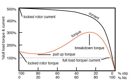
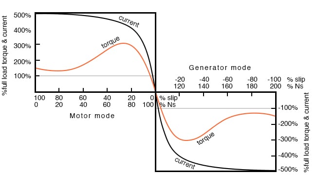
The above graph shows that starting torque known as locked rotor torque (TLR) is higher than 100% of the full load torque (TFL), the safe continuous torque rating. The locked rotor torque is about 175% of TFL for the example motor graphed above. Starting current known as locked rotor current (ILR) is 500% of full load current (IFL), the safe running current. The current is high because this is analogous to a shorted secondary on a transformer. As the rotor starts to rotate the torque may decrease a bit for certain classes of motors to a value known as the pull-up torque. This is the lowest value of torque ever encountered by the starting motor. As the rotor gains 80% of synchronous speed, torque increases from 175% up to 300% of the full load torque. This breakdown torque (TBD) is due to the larger than normal 20% slip. The current has decreased only slightly at this point but will decrease rapidly beyond this point. As the rotor accelerates to within a few percents of synchronous speed, both torque and current will decrease substantially. Slip will be only a few percents during normal operation. For a running motor, any portion of the torque curve below 100% rated torque is normal. The motor load determines the operating point on the torque curve. While the motor torque and current may exceed 100% for a few seconds during starting, continuous operation above 100% can damage the motor. Any motor torque load above the breakdown torque will stall the motor. The torque, slip, and current will approach zero for a “no mechanical torque” load condition. This condition is analogous to an open secondary transformer. There are several basic induction motor designs showing considerable variation from the torque curve above. The different designs are optimized for starting and running different types of loads. The locked rotor torque (TLR) for various motor designs and sizes ranges from 60% to 350% of full load torque (TFL). Starting current or locked rotor current (ILR) can range from 500% to 1400% of full load current (IFL). This current draw can present a starting problem for large induction motors.
NEMA and IEC Motor Classes
Various standard classes (or designs) for motors, corresponding to the torque curves (figure below) have been developed to better drive various type loads. The National Electrical Manufacturers Association (NEMA) has specified motor classes A, B, C, and D to meet these drive requirements. Similar International Electrotechnical Commission (IEC) classes N and H correspond to NEMA B and C designs respectively.
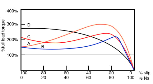
Characteristics for NEMA designs
All motors, except class D, operate at 5% slip or less at full load.
- Class B (IEC Class N) motors are the default motor to use in most applications. With a starting torque of LRT = 150% to 170% of FLT, it can start most loads, without excessive starting current (LRT). Efficiency and power factor are high. It typically drives pumps, fans, and machine tools.
- Class A starting torque is the same as class B. Drop out torque and starting current (LRT) is higher. This motor handles transient overloads as encountered in injection molding machines.
- Class C (IEC Class H) has higher starting torque than class A and B at LRT = 200% of FLT. This motor is applied to hard-starting loads which need to be driven at constant speed like conveyors, crushers, and reciprocating pumps and compressors.
- Class D motors have the highest starting torque (LRT) coupled with low starting current due to high slip ( 5% to 13% at FLT). The high slip results in lower speed. The speed regulation is poor. However, the motor excels at driving highly variable speed loads like those requiring an energy storage flywheel. Applications include punch presses, shears, and elevators.
- Class E motors are a higher efficiency version of class B.
- Class F motors have much lower LRC, LRT, and break down torque than class B. They drive constant, easily started loads.
Power Factor in Induction Motors
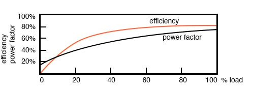
Induction motors present a lagging (inductive) power factor to the power line. The power factor in large fully loaded high-speed motors can be as favorable as 90% for large high-speed motors. At 3/4 full load, the largest high-speed motor power factor can be 92%. The power factor for small low-speed motors can be as low as 50%. At starting, the power factor can be in the range of 10% to 25%, rising as the rotor achieves speed.Power factor (PF) varies considerably with the motor mechanical load (figure below). An unloaded motor is analogous to a transformer with no resistive load on the secondary. Little resistance is reflected from the secondary (rotor) to the primary (stator). Thus the power line sees a reactive load, as low as 10% PF. As the rotor is loaded an increasing resistive component is reflected from the rotor to stator, increasing the power factor.
Efficiency in Induction Motors
Large three-phase motors are more efficient than smaller 3-phase motors, and most all single-phase motors. Large induction motor efficiency can be as high as 95% at full load, though 90% is more common. Efficiency for a lightly loaded or no-loaded induction motor is poor because most of the current is involved with maintaining the magnetizing flux. As the torque load is increased, more current is consumed in generating torque, while current associated with magnetizing remains fixed. Efficiency at 75% FLT can be slightly higher than that at 100% FLT. Efficiency is decreased a few percents at 50% FLT and decreased a few more percents at 25% FLT. Efficiency only becomes poor below 25% FLT. The variation of efficiency with loading is shown in the figure above.Induction motors are typically oversized to guarantee that their mechanical load can be started and driven under all operating conditions. If a polyphase motor is loaded at less than 75% of rated torque where efficiency peaks, efficiency suffers only slightly down to 25% FLT.
Nola Power Factor Corrector
Frank Nola of NASA proposed a power factor corrector (PFC) as an energy-saving device for single-phase induction motors in the late 1970s. It is based on the premise that a less than fully loaded induction motor is less efficient and has a lower power factor than a fully-loaded motor. Thus, there is energy to be saved in partially loaded motors, 1-φ motors in particular. The energy consumed in maintaining the stator magnetic field is relatively fixed with respect to load changes. While there is nothing to be saved in a fully-loaded motor, the voltage to a partially loaded motor may be reduced to decrease the energy required to maintain the magnetic field. This will increase the power factor and efficiency. This was a good concept for the notoriously inefficient single phase motors for which it was intended.This concept is not very applicable to large 3-phase motors. Because of their high efficiency (90%+), there is not much energy to be saved. Moreover, a 95% efficient motor is still 94% efficient at 50% full load torque (FLT) and 90% efficient at 25% FLT. The potential energy savings in going from 100% FLT to 25% FLT is the difference in efficiency 95% – 90% = 5%. This is not 5% of the full load wattage but 5% of the wattage at the reduced load. The Nola power factor corrector might be applicable to a 3-phase motor which idles most of the time (below 25% FLT), like a punch press. The payback period for the expensive electronic controller has been estimated to be unattractive for most applications. Though, it might be economical as part of an electronic motor starter or speed Control.An induction motor may function as an alternator if it is drive
Induction Motors as Alternators
An induction motor may function as an alternator if it is driven by a torque at greater than 100% of the synchronous speed (figure below). This corresponds to a few % of “negative” slip, say -1% slip. This means that as we are rotating the motor faster than the synchronous speed, the rotor is advancing 1% faster than the stator rotating magnetic field. It normally lags by 1% in a motor. Since the rotor is cutting the stator magnetic field in the opposite direction (leading), the rotor induces a voltage into the stator feeding electrical energy back into the power line.
Such an induction generator must be excited by a “live” source of 50 or 60 Hz power. No power can be generated in the event of a power company power failure. This type of alternator appears to be unsuited as a standby power source. As an auxiliary power wind turbine generator, it has the advantage of not requiring an automatic power failure disconnect switch to protect repair crews. It is fail-safe.
Small remote (from the power grid) installations may be made self-exciting by placing capacitors in parallel with the stator phases. If the load is removed residual magnetism may generate a small amount of current flow. This current is allowed to flow by the capacitors without dissipating power. As the generator is brought up to full speed, the current flow increases to supply a magnetizing current to the stator. The load may be applied at this point. Voltage regulation is poor. An induction motor may be converted to a self-excited generator by the addition of capacitors.
Startup procedure is to bring the wind turbine up to speed in motor mode by application of normal power line voltage to the stator. Any wind-induced turbine speed in excess of synchronous speed will develop negative torque, feeding power back into the power line, reversing the normal direction of the electric kilowatt-hour meter. Whereas an induction motor presents a lagging power factor to the power line, an induction alternator presents a leading power factor. Induction generators are not widely used in conventional power plants. The speed of the steam turbine drive is steady and controllable as required by synchronous alternators. Synchronous alternators are also more efficient.
The speed of a wind turbine is difficult to control and subject to wind speed variation by gusts. An induction alternator is better able to cope with these variations due to the inherent slip. This stresses the gear train and mechanical components less than a synchronous generator. However, this allowable speed variation only amounts to about 1%. Thus, a direct line connected induction generator is considered to be fixed-speed in a wind turbine (See Doubly-fed induction generator for a true variable speed alternator). Multiple generators or multiple windings on a common shaft may be switched to provide a high and low speed to accommodate variable wind conditions.
Induction Motors with Multiple Fields
Induction motors may contain multiple field windings, for example, a 4-pole and an 8-pole winding corresponding to 1800 and 900 rpm synchronous speeds. Energizing one field or the other is less complex than rewiring the stator coils.
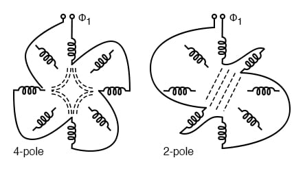
If the field is segmented with leads brought out, it may be rewired (or switched) from 4-pole to 2-pole as shown above for a 2-phase motor. The 22.5° segments are switchable to 45° segments. Only the wiring for one phase is shown above for clarity. Thus, our induction motor may run at multiple speeds. When switching the above 60 Hz motor from 4 poles to 2 poles the synchronous speed increases from 1800 rpm to 3600 rpm.
Q: If the motor is driven by 50 Hz, what would be the corresponding 4-pole and 2-pole synchronous speeds?
A:
[latex]N_s = \frac{120f}{P}[/latex] [latex]N_s = \frac{120*50Hz}{4}[/latex] [latex]= 1500 rpm(4-pole)[/latex]
[latex]N_s = \frac{120f}{P}[/latex] [latex]N_s = \frac{120*50Hz}{2}[/latex][latex]= 3000 rpm (2-pole)[/latex]
Induction Motors with Variable Voltage
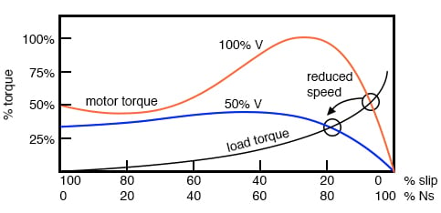
The speed of small squirrel cage induction motors for applications such as driving fans may be changed by reducing the line voltage. This reduces the torque available to the load which reduces the speed (see figure below).
Electronic Speed Control in Induction Motors
Modern solid-state electronics increase the options for speed control. By changing the 50 or 60 Hz line frequency to higher or lower values, the synchronous speed of the motor may be changed. However, decreasing the frequency of the current fed to the motor also decreases reactance XL which increases the stator current. This may cause the stator magnetic circuit to saturate with disastrous results. In practice, the voltage to the motor needs to be decreased when the frequency is decreased.
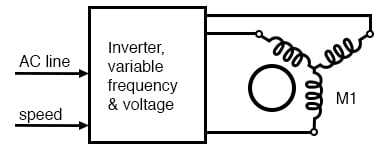
Conversely, the drive frequency may be increased to increase the synchronous speed of the motor. However, the voltage needs to be increased to overcome increasing reactance to keep current up to a normal value and maintain torque. The inverter approximates sine waves to the motor with pulse width modulation outputs. This is a chopped waveform which is either on or off, high or low, the percentage of “on” time corresponds to the instantaneous sine wave voltage.
Once electronics is applied to induction motor control, many control methods are available, varying from the simple to complex:
- Scalar Control: Low-cost method described above to control only voltage and frequency, without feedback.
- Vector Control: Also known as a vector phase control. The flux and torque producing components of stator current are measured or estimated on a real-time basis to enhance the motor torque-speed curve. This is computation intensive.
- Direct Torque Control: An elaborate adaptive motor model allows more direct control of flux and torque without feedback. This method quickly responds to load changes.
- A polyphase induction motor consists of a polyphase winding embedded in a laminated stator and a conductive squirrel-cage embedded in a laminated rotor.
- Three-phase currents flowing within the stator create a rotating magnetic field which induces a current and consequent magnetic field in the rotor. Rotor torque is developed as the rotor slips a little behind the rotating stator field.
- Unlike single-phase motors, polyphase induction motors are self-starting.
- Motor starters minimize loading of the power line while providing a larger starting torque than required during running. Line current reducing starters are only required for large motors.
- Three-phase motors will run on single phase if started.
- A static phase converter is a three-phase motor running on single phase having no shaft load, generating a 3-phase output.
- Multiple field windings can be rewired for multiple discrete motor speeds by changing the number of poles.
5.3 Single-phase Induction Motors
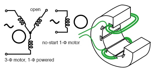
A three-phase motor may be run from a single-phase power source. However, it will not self-start. It may be hand started in either direction, coming up to speed in a few seconds. It will only develop 2/3 of the 3-φ power rating because one winding is not used.
Single Coil of a Single Phase Motor
The single coil of a single-phase induction motor does not produce a rotating magnetic field, but a pulsating field reaching maximum intensity at 0° and 180° electrical.

Another view is that the single-coil excited by a single-phase current produces two counter-rotating magnetic field phasors, coinciding twice per revolution at 0° (Figure above-a) and 180° (figure e). When the phasors rotate to 90° and -90° they cancel in figure c. At 45° and -45° (figure b) they are partially additive along the +x axis and cancel along the y-axis. An analogous situation exists in figure d. The sum of these two phasors is a phasor stationary in space, but alternating polarity in time. Thus, no starting torque is developed.
However, if the rotor is rotated forward at a bit less than the synchronous speed, It will develop maximum torque at 10% slip with respect to the forward rotating phasor. Less torque will be developed above or below 10% slip. The rotor will see 200% – 10% slip with respect to the counter-rotating magnetic field phasor. Little torque (see torque vs slip curve) other than a double frequency ripple is developed from the counter-rotating phasor. Thus, the single-phase coil will develop torque, once the rotor is started. If the rotor is started in the reverse direction, it will develop a similar large torque as it nears the speed of the backward rotating phasor.
Single-phase induction motors have a copper or aluminum squirrel cage embedded in a cylinder of steel laminations, typical of polyphase induction motors.
Permanent-Split Capacitor Motor
One way to solve the single phase problem is to build a 2-phase motor, deriving 2-phase power from single phase. This requires a motor with two windings spaced apart 90° electrical, fed with two phases of current displaced 90° in time. This is called a permanent-split capacitor motor.

Permanent-split capacitor induction motor
This type of motor suffers increased current magnitude and backward time shift as the motor comes up to speed, with torque pulsations at full speed. The solution is to keep the capacitor (impedance) small to minimize losses. The losses are less than for a shaded pole motor. This motor configuration works well up to 1/4 horsepower (200 watts), though, usually applied to smaller motors. The direction of the motor is easily reversed by switching the capacitor in series with the other winding. This type of motor can be adapted for use as a servo motor, described elsewhere in this chapter.
Single-phase induction motors may have coils embedded into the stator for larger size motors. Though, the smaller sizes use less complex to build concentrated windings with salient poles.
Capacitor-Start Induction Motor
In the figure below a larger capacitor may be used to start a single-phase induction motor via the auxiliary winding if it is switched out by a centrifugal switch once the motor is up to speed. Moreover, the auxiliary winding may be many more turns of heavier wire than used in a resistance split-phase motor to mitigate excessive temperature rise. The result is that more starting torque is available for heavy loads like air conditioning compressors. This motor configuration works so well that it is available in multi-horsepower (multi-kilowatt) sizes.

Capacitor-Run Motor Induction Motor
A variation of the capacitor-start motor (figure below) is to start the motor with a relatively large capacitor for high starting torque, but leave a smaller value capacitor in place after starting to improve running characteristics while not drawing excessive current. The additional complexity of the capacitor-run motor is justified for larger size motors.

A motor starting capacitor may be a double-anode non-polar electrolytic capacitor which could be two + to + (or – to -) series-connected polarized electrolytic capacitors. Such AC rated electrolytic capacitors have such high losses that they can only be used for intermittent duty (1 second on, 60 seconds off) like motor starting. A capacitor for motor running must not be of electrolytic construction, but a lower loss polymer type.
Resistance Split-Phase Motor Induction Motor
If an auxiliary winding of much fewer turns, a smaller wire is placed at 90°electrical to the main winding, it can start a single-phase induction motor. With lower inductance and higher resistance, the current will experience less phase shift than the main winding. About 30° of phase difference may be obtained. This coil produces a moderate starting torque, which is disconnected by a centrifugal switch at 3/4 of synchronous speed. This simple (no capacitor) arrangement serves well for motors up to 1/3 horsepower (250 watts) driving easily started loads.
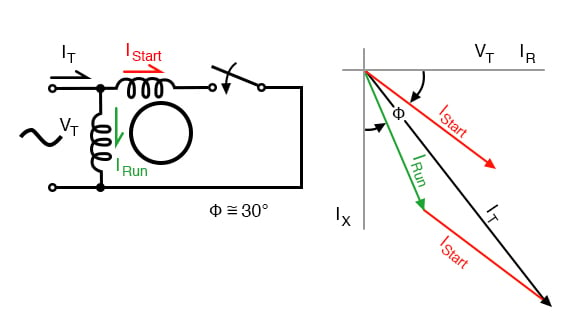
This motor has more starting torque than a shaded pole motor (next section), but not as much as a two-phase motor built from the same parts. The current density in the auxiliary winding is so high during starting that the consequent rapid temperature rise precludes frequent restarting or slow starting loads.
Nola Power Factor Corrector
Frank Nola of NASA proposed a power factor corrector for improving the efficiency of AC induction motors in the mid-1970s. It is based on the premise that induction motors are inefficient at less than full load. This inefficiency correlates with a low power factor. The less than unity power factor is due to magnetizing current required by the stator. This fixed current is a larger proportion of total motor current as the motor load is decreased. At light load, the full magnetizing current is not required. It could be reduced by decreasing the applied voltage, improving the power factor and efficiency. The power factor corrector senses power factor, and decreases motor voltage, thus restoring a higher power factor and decreasing losses.
Since single-phase motors are about 2 to 4 times as inefficient as three-phase motors, there are potential energy savings for 1-φ motors. There are no savings for a fully-loaded motor since all the stator magnetizing current is required. The voltage cannot be reduced. But there are potential savings from a less than fully loaded motor. A nominal 117 VAC motor is designed to work at as high as 127 VAC, as low as 104 VAC. That means that it is not fully loaded when operated at greater than 104 VAC, for example, a 117 VAC refrigerator. It is safe for the power factor controller to lower the line voltage to 104-110 VAC. The higher the initial line voltage, the greater the potential savings. Of course, if the power company delivers closer to 110 VAC, the motor will operate more efficiently without any add-on device.
Any substantially idle, 25% FLC or less, a single-phase induction motor is a candidate for a PFC. Though, it needs to operate a large number of hours per year. And the more time it idles, as in lumber saw, punch press, or conveyor, the greater the possibility of paying for the controller in a few years operation. It should be easier to pay for it by a factor of three as compared to the more efficient 3-φ-motor. The cost of a PFC cannot be recovered for a motor operating only a few hours per day.
Summary: Single-phase induction motors
- Single-phase induction motors are not self-starting without an auxiliary stator winding driven by an out of phase current of near 90°. Once started the auxiliary winding is optional.
- The auxiliary winding of a permanent split capacitor motor has a capacitor in series with it during starting and running.
- A capacitor-start induction motor only has a capacitor in series with the auxiliary winding during starting.
- A capacitor-run motor typically has a large non-polarized electrolytic capacitor in series with the auxiliary winding for starting, then a smaller non-electrolytic capacitor during running.
- The auxiliary winding of a resistance split-phase motor develops a phase difference versus the main winding during starting by virtue of the difference in resistance.