
Part Two. Revit
Chapter 14. Add/edit windows, doors, lighting fixtures, furniture, tags, & sheets
Upon completing this session, students will be able to:
- (CO 1) Understand the concept of family file
- (CO 2) Add/Edit Doors and Windows
- (CO 3) Add Tags
- (CO 4) Add/Edit Lighting fixtures
- (CO 5) Add/Edit Titleblocks
- (CO 6) Insert Plan views and symbols – North arrow and graphic scale
 Session Highlights
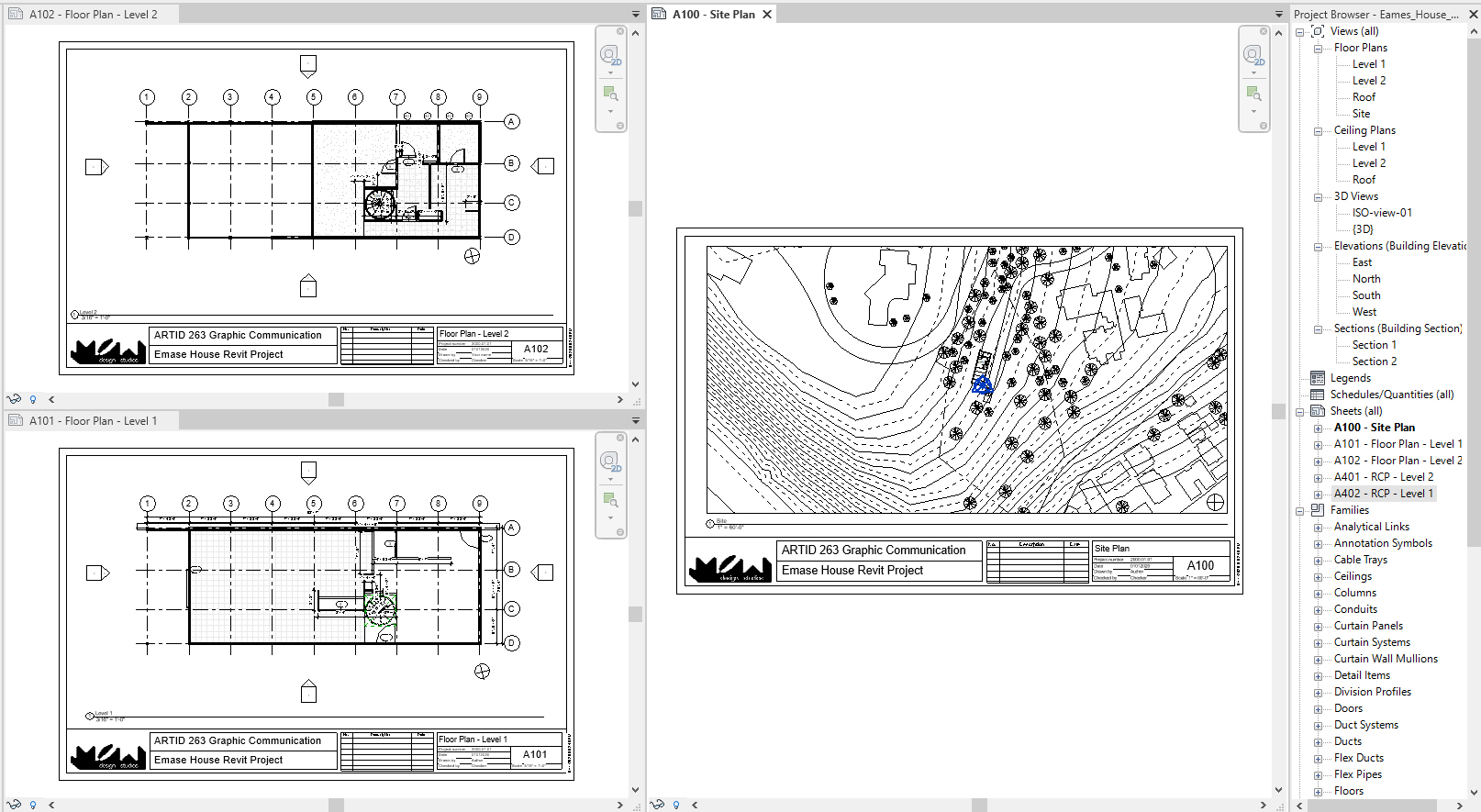
At the end of the session, students can create the graphics below.
 Lecture Contents
(CO 1) Understand the concept of family file
About Revit Families
- A Revit family is a group of elements with a common set of properties, called parameters, and a related graphical representation
- All of the elements that you add to your Revit projects are created with families.
- For example, the structural members, walls, roofs, windows, and doors that you use to assemble a building model, as well as the callouts, fixtures, tags, and detail components that you use to document it, are all created with families.
For more information about the Revit family, please see this page Autodesk Knowledge – Revit Family
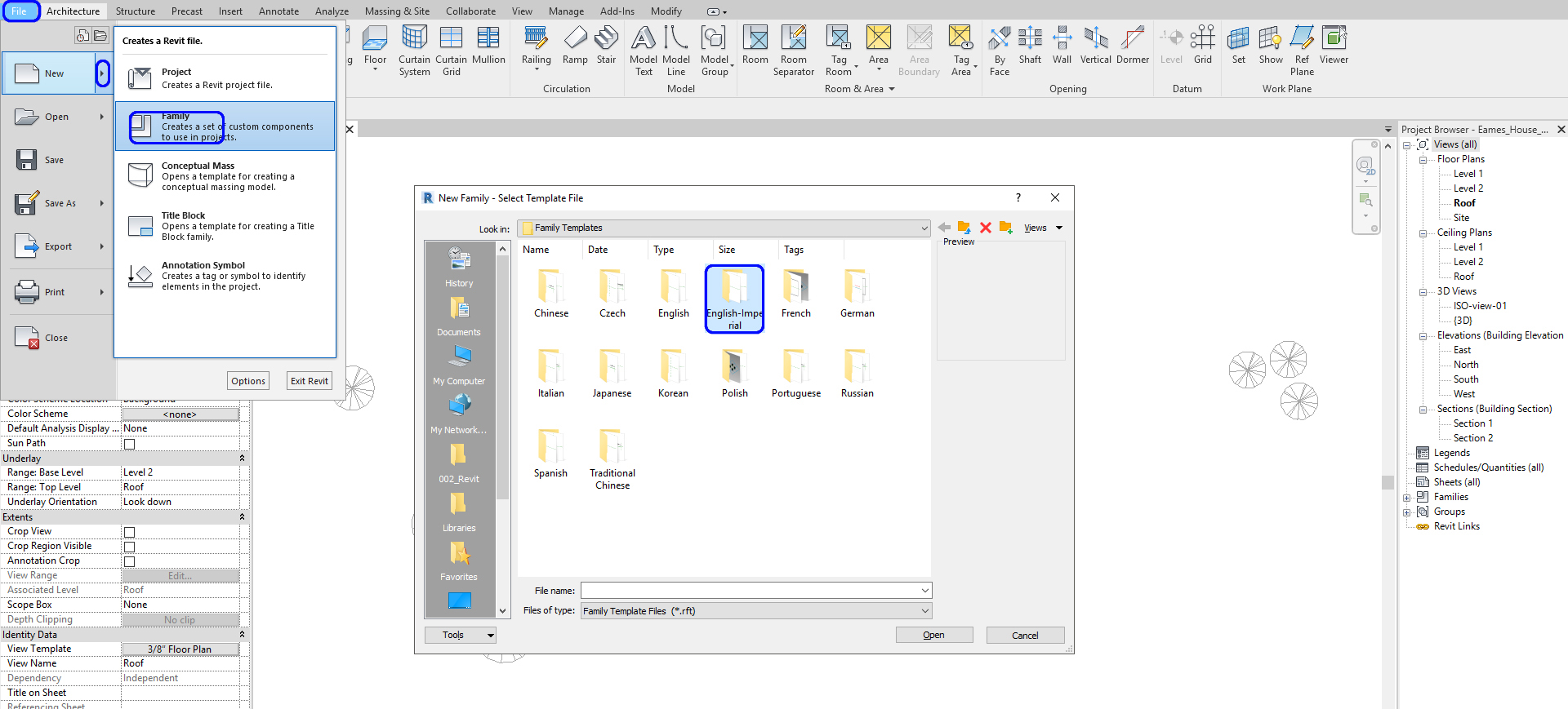
To create a new family
- Click [File] on the menu > Click [New] > Click [Family] > Select a template from library > create the model and parameter
- However, A beginner may elect to not create a new family due to the complexity of the process. Instead, you may want to start with a family that has similar attributes and edit accordingly.
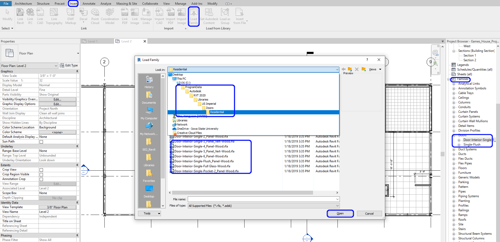
To load Family files from the Revit library
- Click [Load Family] from [Insert] tab, under [Load from Library] panel > Find the library folder from your computer > Select a family / families to load > Click [OPEN]
- Then, you can confirm and find the loaded families from the [Project Browser] under the [Family] category
- You can load as many families as possible but you should consider file size.
Find and download Revit families from external sources (recommended websites by the instructor)
- BimObject https://www.bimobject.com/en-us
- Manufacturer upload Revit Family files
- Previously named Autodesk Seek
- Most of the files are reliable, some advertisements added
- Revit City https://www.revitcity.com/index.php
- The user shared Revit Family website
- Many designers, practitioners, and students use this website
- Some files may cause issues to your project
- BIM Smith https://market.bimsmith.com/
- Mix of free and paid Revit Families
- Great collection of products
- NBS National BIM Library https://www.nationalbimlibrary.com/en/
- UK based the best BIM object website
- Manufacturers website
- Most reliable but hard to find out
Top 15 sites with free Revit Families by Karl Tanner, created February 3. 2019, updated in December 2020. https://revitiq.com/top-15-sites-free-revit-families/
Revit families from Furniture manufacturers’ websites.
- Allsteel
- Hon
- HBF
- Gunlocke
- Herman Miller
- Knoll
- Haworth
- Steelcase
- Krueger International (KI)
- Sandler
- Tonik
- Hightower
- Bernhardt
- Martin Brattrud
- Vitra
- Andreu World
- Emeco
- Decco Contract
- Stylex Seating
- Kimball
- Keilhauer
- B&B Italia
- Palmer Hamilton
- Cumberland
- Zenith Interiors
- Falcon
- Shelby Williams
- Global Furniture Group
- Carolina
- Kwalu
Purge Revit families
- Family management is one of the keys to managing your Revit file. If you want to delete unused family files, click [Purge Unused] from the Manage tab.
- Use caution when using this function; you will lose all family and views you are not using. I recommend you make a copy or save as the original file and [Purge Unused].
- Click [Purge Unused] Number of items checked until “0”.
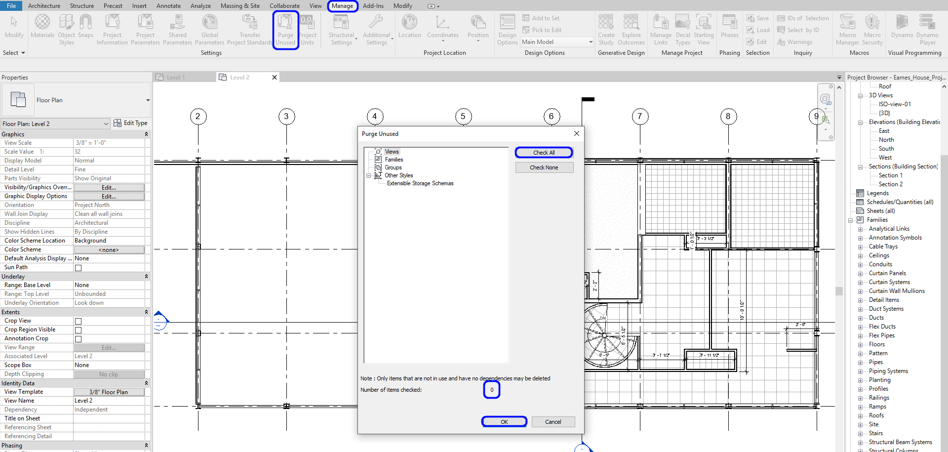
- The file size reduced, then you have a lighter file to handle

(CO 2) Add/Edit Doors and Windows
Add a door on a Wall
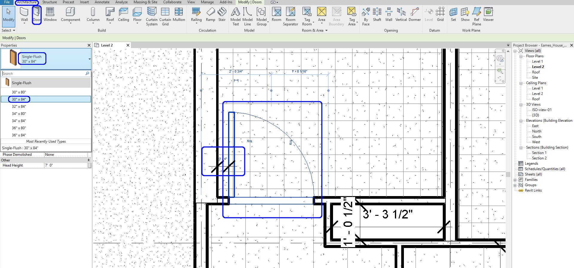
- [STEP 1] Click [Door] from the [Architecture] tab, under [Built] panel
or press [DR] as a shortcut - [STEP 2] Select door type from the [Properties] palette.
- If you need to load a new type, click the [Modify/Place Door] tab and click [Load Family], Double click [Doors] Folder, find out the family that you want from the sub-folders
- If you cannot find the door family that you want, you may search on various websites above and load into the project file
- If you found the type you want, but you do not find the size of the door, you click [Edit Type] and Duplicate the type and change the values
- [STEP 3] Place the door near the wall. Use [Space bar] to change the direction of the door. It shows the location of the door that will be placed. Click the location that you want.
- [STEP 4] Once you placed the door, you can change the direction by clicking arrows, and you can change the exact location of the door. Typically, the distance between the wall to the door is 4.”
- [STEP 5] If you need to change the door type, click and change the type from the Properties panel
Complete to add all doors in the floor plans for the project
Add a window on a wall
- [STEP 1] Click [Window] from the [Architecture] tab, under [Build] panel
or, press [WN] as a shortcut - [STEP 2] Select a window type from the [Properties] palette.
- [STEP 3] Adding a window is the same sequence as adding a door.
- [STEP 4] You can modify the sill height when you add a window.
The Eames House project doesn’t have a window.
Add a skylight on a roof
- [STEP 1] Click [Window] from the [Architecture] tab
or press [WN] as a shortcut - [STEP 2] If you do not find a skylight from the [Properties] palette, click [Load family] > find the Skylight family under the Window folder from the Revit library > click [Open]
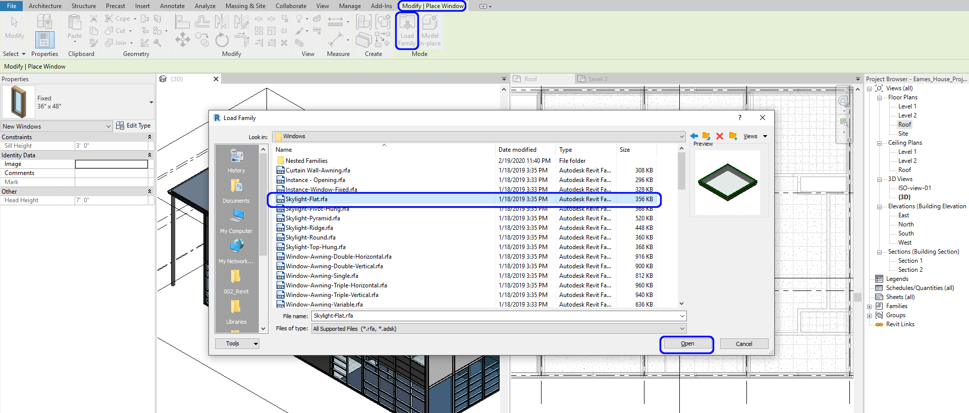
- [STEP 3] The Skylight for Eames House is 5’X5’ Flat, so the type should be made by duplicating the existing one.
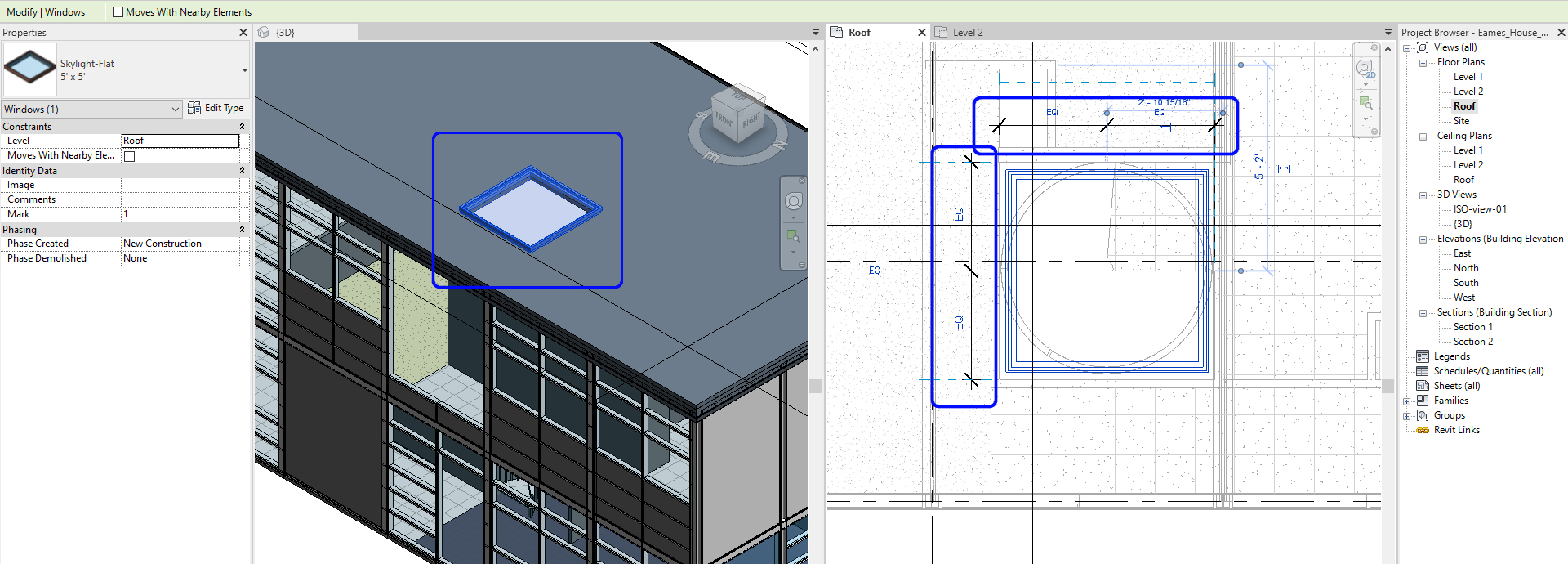
- [STEP 4] Open [3D view] > click the appropriate location where the skylight is supposed to be located > open [Roof] view > update location of the skylight with dimensions
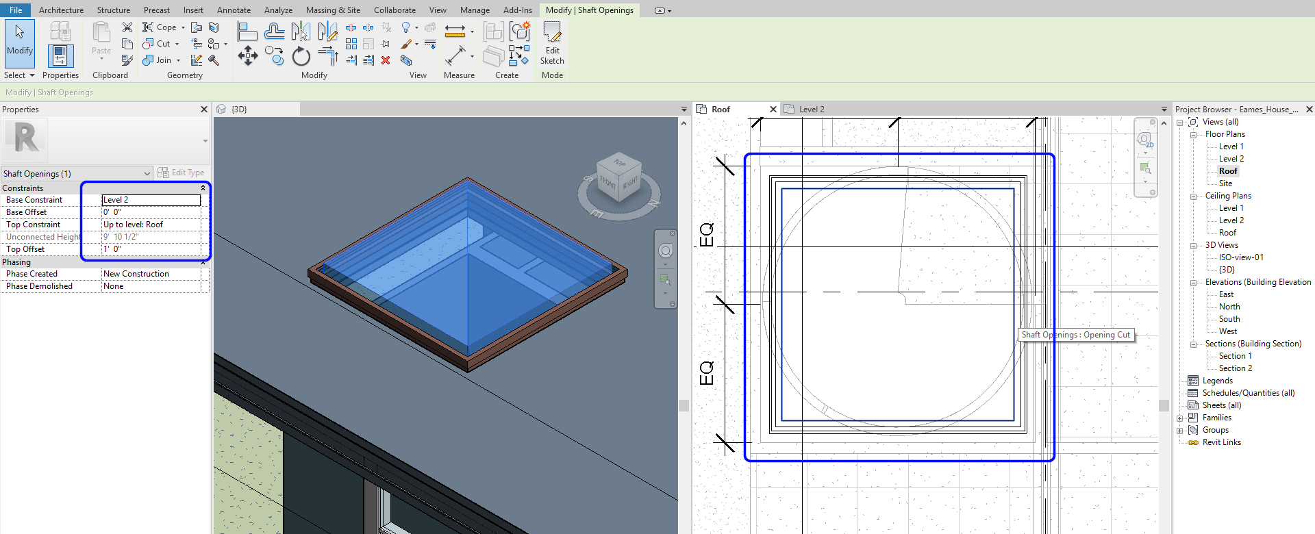
- [STEP 5] You may notice that the skylight only opens the roof, not the ceilings you may make. You must make a hole to open the ceilings. Click [Shaft] from the [Architecture] tab, under [Openning] panel > Open the plan below the roof level. For Eames house, it is Level 2 > Draw the opening. It must be a little smaller than the skylight size and click the [green checkmark]
- [STEP 6] Make sure the base constraint is Level 2, and the Top constraint is Up to Level: Roof, Top Offset 1’. Relocate the Skylight.
Note. If [Shaft] tool is not working, please try this
- Click [Edit In-Place] > Click [Void Forms] > Select [Void Extrusion] from [Create] tab > Draw lines > click the [Green checkmark] to finish and double-check the void penetrate
Add a door / a window on a curtain wall
- [STEP 1] Adding a curtain wall door or window is not under the Door or Window from the [Architecture] tab. To switch a panel to a door or a window, you must select the panel first by pressing the [Tab] key.
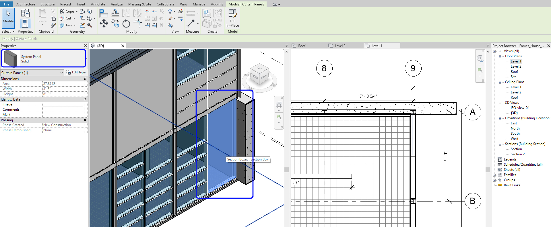
- [STEP 2] You might find the door from the [Properties] palette.
- If the curtain wall door was not loaded, you need to load the door first and then change the properties palette.
- To load the door family, click [Load Family] from the [Insert] tab
- Find “Door-Curtain-Wall-Single-Glass.rfa” from the Doors folder > Open
- Find “Curtain Wall-Awning.rfa” from the Windows folder > Open
- Find “Sliding_Curtain_Wall_Door_12253.rfa” from Canvas and download to your project folder > Open
- [STEP 3] Change the type from the properties palette.
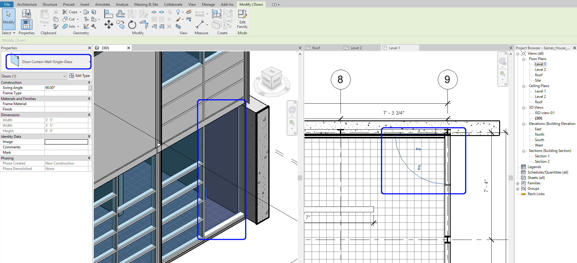
Complete to update all curtainwall doors and curtainwall windows for the project
(CO 3) Add Tags
Add door and window tags
- [STEP 1] Click [Tag by Category] from the [Annotate] tab, under [Tag] panel
or (TG) for the shortcut - [STEP 2] The Door tag setting can be made a distance (1/4”) from the door
- [STEP 3] Once you click a door, the tag will show
- [STEP 4] The number may show or may not show. If not, you can make a number
- [STEP 5] You can also tag both the curtain wall door and windows with a door and window tag.
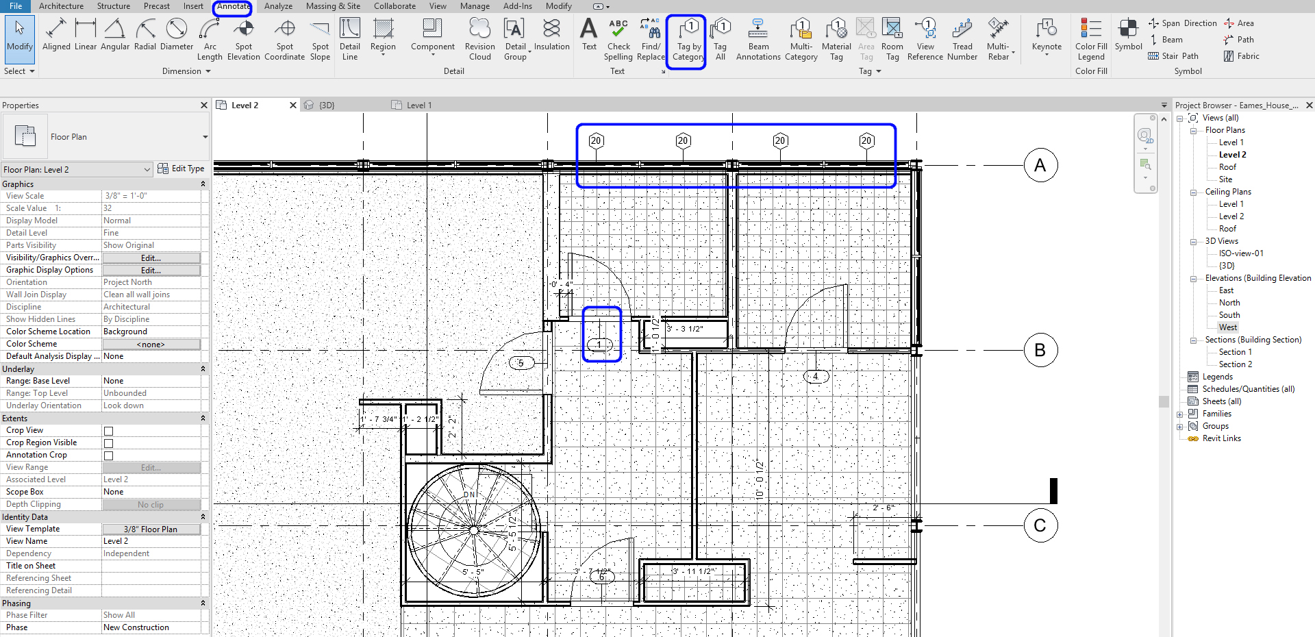
Complete to update all tags for doors and windows for the project
(CO 4) Add/Edit Lighting fixtures
Load Lighting Fixtures
Load Lighting families by clicking Load Family. You can find Revit lighting families from Lighting > Architectural > Internal folder from the Revit library. You can load all lighting fixtures from the folder or only selected lighting fixtures to your project.
If you want a unique lighting fixture, please download it from various websites and save it in your project folder for future use.
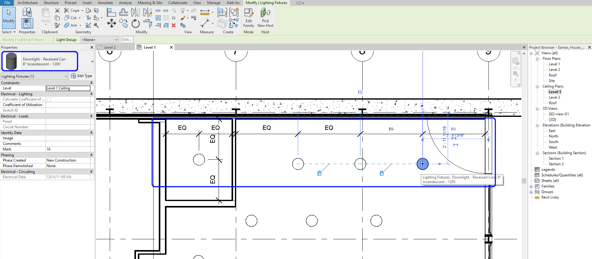
Add Lighting fixtures
- [STEP 1] Open [Level 1] Ceiling plan from the [Project Browser]
- [STEP 2] Click [Component] (CM) to place lighting fixtures from the [Architecture] tab
- [STEP 3] Select a family and a family type that you want to add on your ceiling plan. You can search the Lighting family as well
- [STEP 4] Select [Downlight – Recessed Can]
- [STEP 5] Place the lighting fixture on the Utility room ceiling. You may need to switch the placement option. Does not need to be accurate.
- [STEP 6] Make dimensions (DM) and use Align (AL) for the accurate dimension
To see the floor plan for the positioning of the furniture, Select Level 1 for Base Level, Leve 2 for Top-level, “lookup” for Underlay orientation, and then you can see the floor plan on your ceiling plan for lighting layout.
Complete lighting layout with dimensions on the ceiling plans
(CO 5) Add/Edit Titleblocks
Create sheets
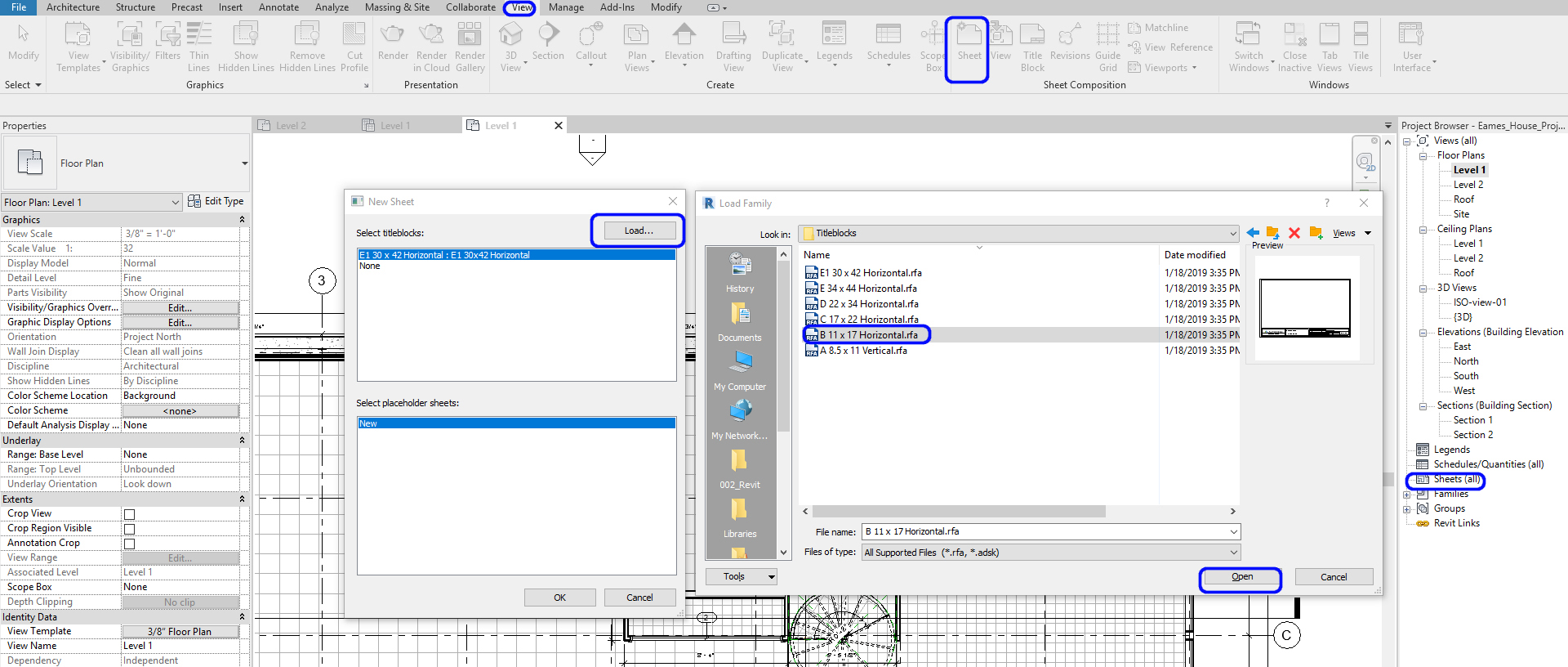
- [STEP 1] Click [Sheet] from the [view] tab, under [Sheet Composition] panel
- [STEP 2] New Sheet window will pop up to create sheets in your project. Click [Load…].
- [STEP 3] The load Family browser will pop up. Find [Titleblocks] folder > Open [B 11 x 17 Horizontal] file > click [OK] > Click [OK] to load on your project file.
- [STEP 4] You can find your A101 – Unnamed on your project browser, once you click [+] mark next to [sheet (all)]
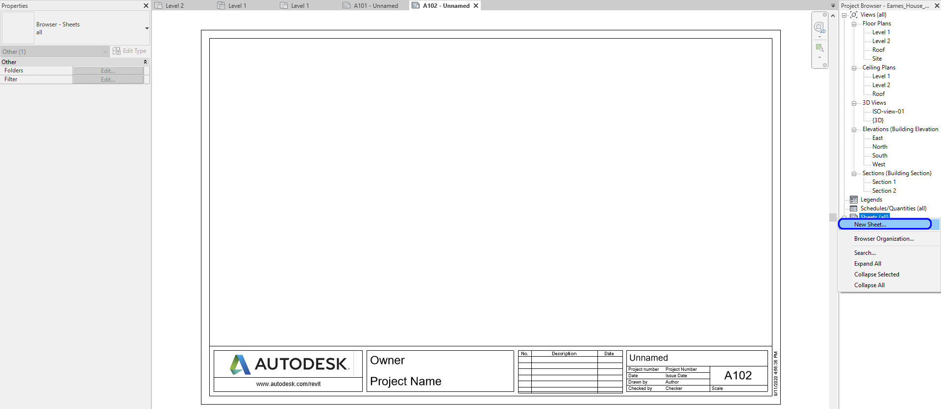
- [STEP 5] If you need more sheets for other views, you can click sheet] from the [View] tab, or you can click the Sheets on Project Browser, and mouse right-click and select New Sheets
- [STEP 6] If you want to change the size of the sheet you already loaded, you can click the title block and change the type on the Properties palette. You can change the Titleblock format that you already loaded
- [STEP 7] On your Titleblock, you should add the project information and the sheet information.
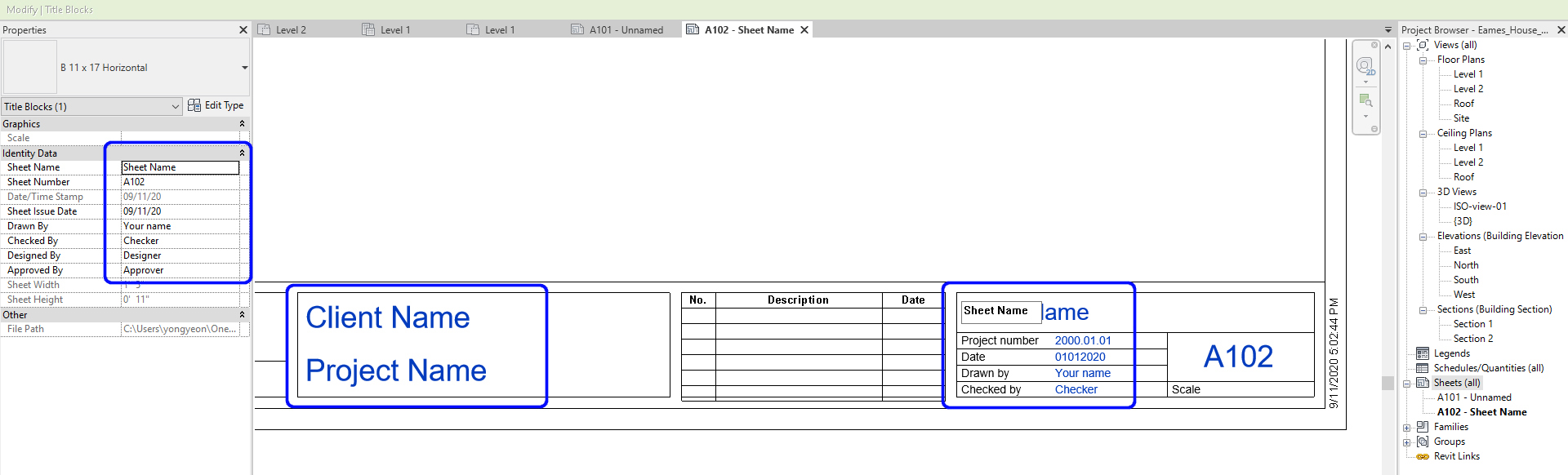
-
- Once you click the Titleblock, you can add more information. Do not double click. If you double click and open the family file, you are editing the family file.
- Under the Owner, we would typically designate the client’s name. In this case, you can add ARTID263
- For Project Name, you can add your project name, Eames House Project
- For Unnamed, it typically designated for the Sheet name, for example, Floor Plan – Level 1, RCP – Level 2, Site Plan, or more
- For Project number, you will make your own. I typically make 20.263.01 (Year.Course number.Project number)
- The issue date will be the submission date
- The author is your name
- Checker is your instructor’s name
Note. This Sheet information will not change even if you change the Titleblock type. And the Project name, Project number, Client, and Issue date will not change even if you add new sheets. But you should add Drawn by and Checked by for all sheets
Edit Titleblocks family file
- [STEP 1] Once you double click the Titleblock, the family file will open
- [STEP 2] I recommend saving this family before you start to edit to preserve the original file.
- Do not forget to add “000” and save the file in your project family folder
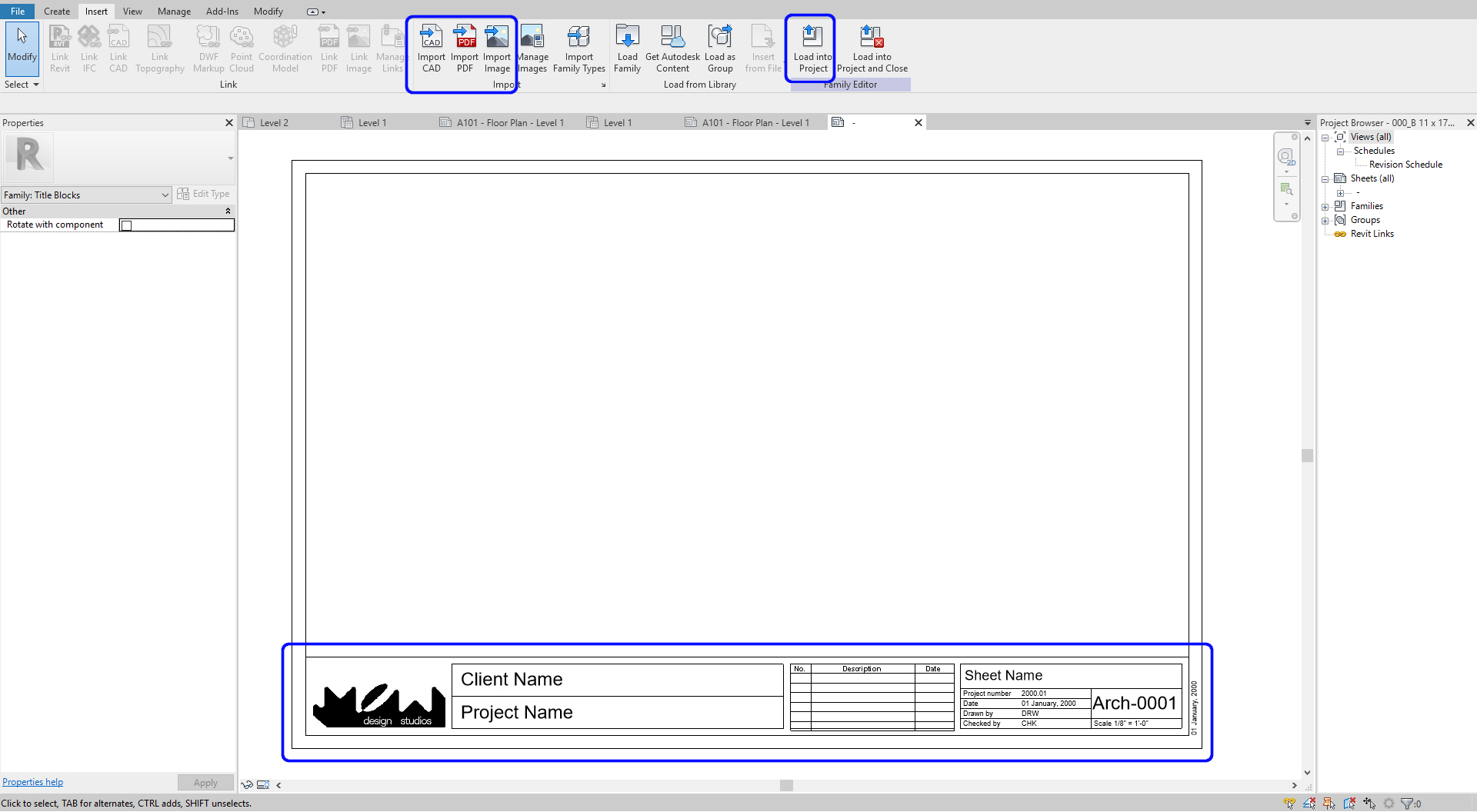
- [STEP 3] You can delete anything in the document. However, I would delete the Autodesk Logo, a line below, and the website information.
- [STEP 4] You can add lines by clicking [Line] from the [Create] tab
- [STEP 5] You can move lines and text box by clicking the elements that you want to move and move (MO) command
- [STEP 6] You can edit lines and text box size as well
- [STEP 7] You can insert images or CAD files by clicking Image or Import CAD from the Insert tab
- [STEP 8] Once you complete your titleblock, you must save and click [Load into Project]
- [STEP 9] After you load the titleblock into your project, you must change the titleblock type to what you made.
(CO 6) Insert Plan views and symbols – North arrow and graphic scale
Insert plans
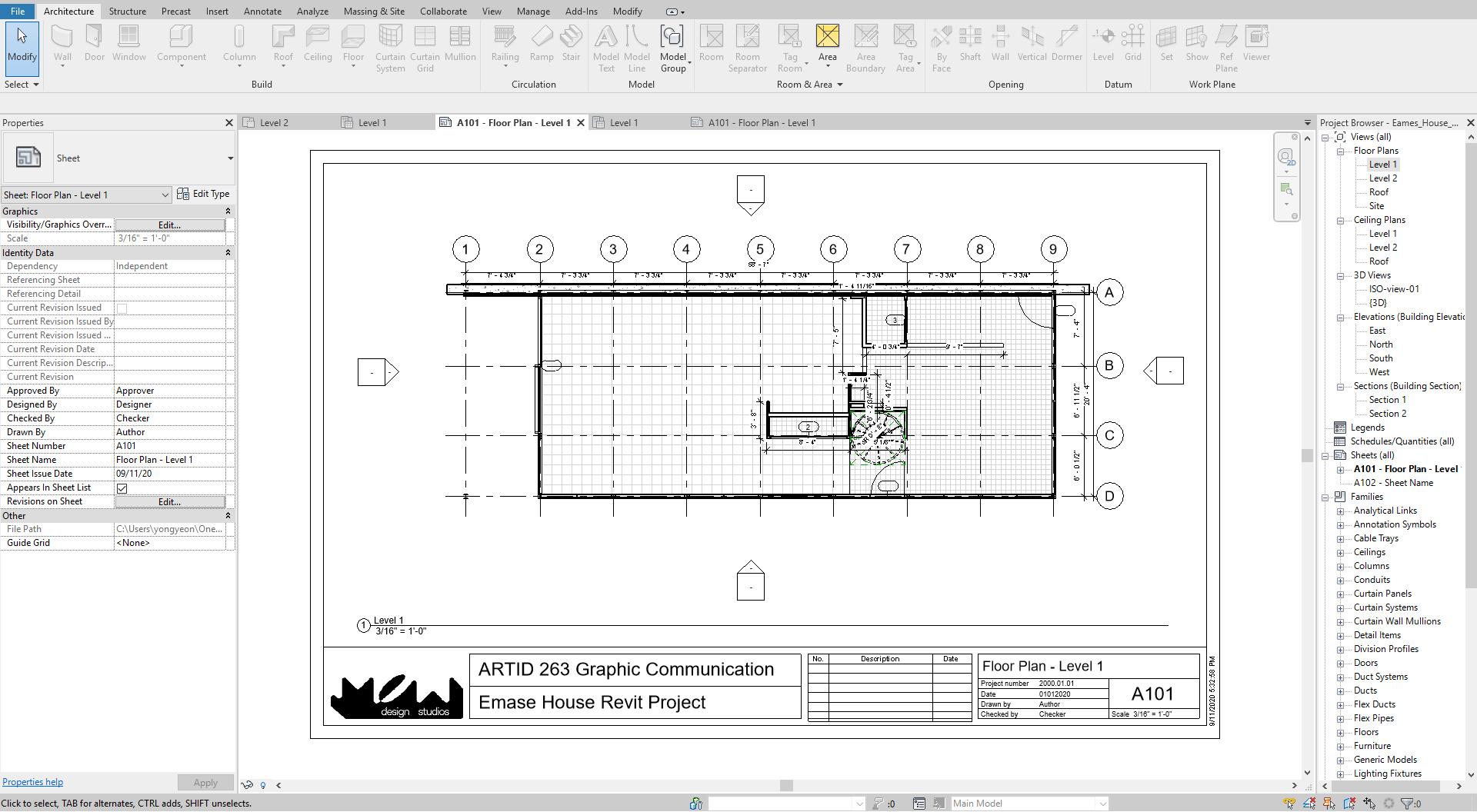
- [STEP 1] Open a sheet [A101-Floor Plan-Level 1] to insert a plan
- [STEP 2] Find the view on your project browser to insert, drag and drop the view to the sheet
- [STEP 3] To fit into the Titleblock, you must change your drawing scale. You can double click and change the scale, or you can change the scale from the Properties palette
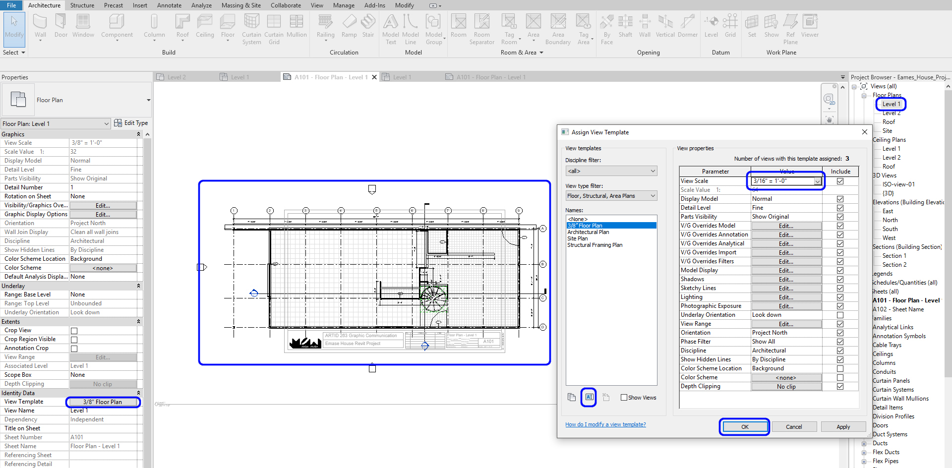
- [STEP 4] Move the view to be centered and change the length of the title bar to fit into the Titleblocks
Repeat this for site plan, floor plans, and ceiling plans
Insert north arrow
- [STEP 1] The north arrow is under Symbol from the [Annotate] tab
- [STEP 2] To add the north arrow, you will open a plan view
- [STEP 3] On the Properties palette, Orientation should be changed from Project North to True North
- [STEP 4] Click Symbol from Annotate tab
- [STEP 5] Select North Arrow 2 on the Properties palette. If you cannot find North Arrow 2, you need to load the North Arrow family from the Annotation folder
- [STEP 6] Place the North Arrow 2 on your plan view
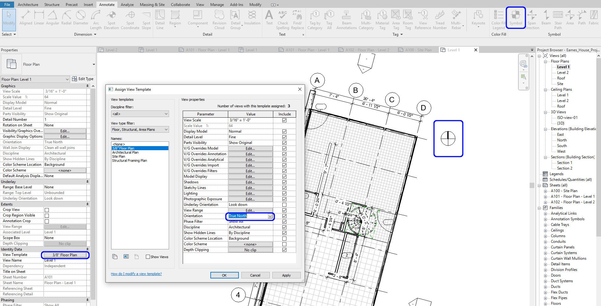
- [STEP 7] Change Orientation again from Ture North to Project North
- [STEP 8] Move the north arrow to the corner of your plan
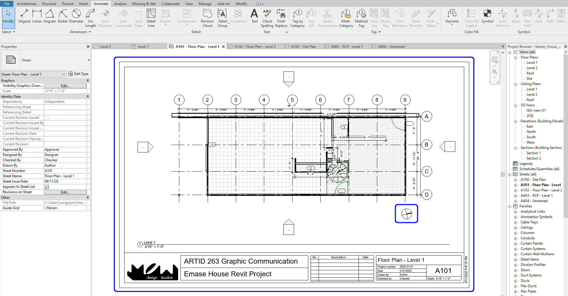
Repeat this for site plan, floor plans, and ceiling plans
SAVE the file before closing the application.
Save in a different location for the backup (e.g., a cloud folder)
 References
Autodesk.Help. (2018, May 16). Revit Families. Retrieved October 22, 2020, from https://knowledge.autodesk.com/support/revit-products/learn-explore/caas/CloudHelp/cloudhelp/2016/ENU/Revit-Model/files/GUID-4EBB97AD-C7B6-4828-91EB-BC0E99B81E43-htm.html
