
Part One. AutoCAD
Chapter 4. Draw elevation and sections
- (CO 1) Draw a section
- (CO 2) Draw an elevation from the floor plan
- (CO 3) Add/Edit Text & Annotation (in model space-annotative) – M Text, Text Style, M leader, and Multileader Style
 Session Highlights
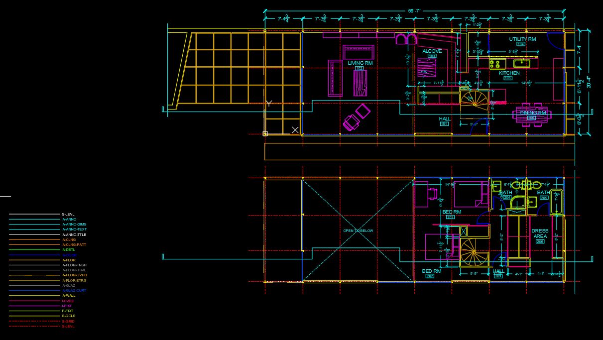
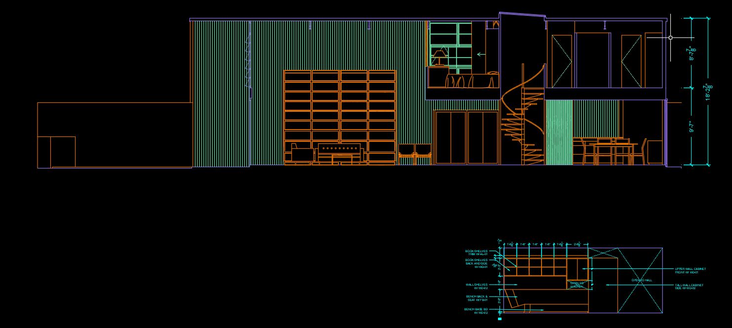
At the end of the session, students can create the graphics below.
 Lecture Contents
(CO 1) Draw a section
“A section is a cut-through of a space that will show more of the room’s features. It also allows you to show some structural detail. A section line can be cut from any part of the space, depending on what you would like to show.”
Retrieved from https://www.nda.ac.uk/blog/identify-plans-elevations-sections/
“A ‘section drawing,’ ‘section,’ or ‘sectional drawing’ shows a view of a structure as though it had been sliced in half or cut along another imaginary plane.”
Retrieved from https://www.designingbuildings.co.uk/wiki/Section_drawing
For more information about a building section drawing, please read this page: https://www.designingbuildings.co.uk/wiki/Section_drawing
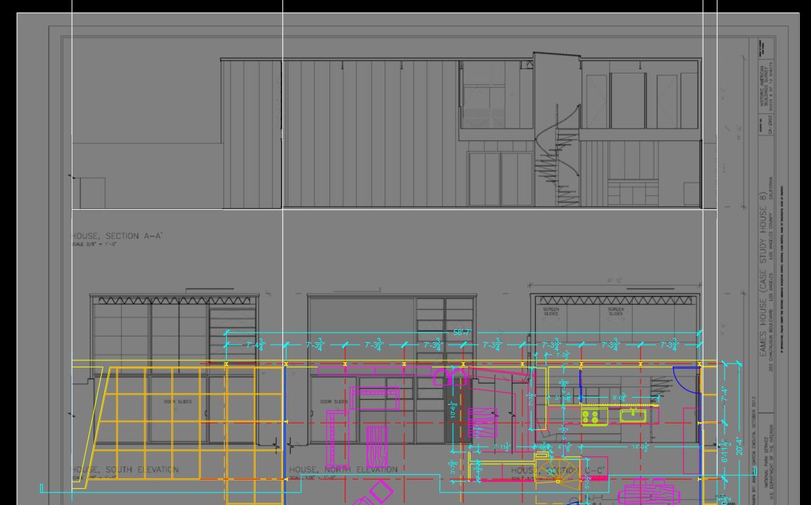
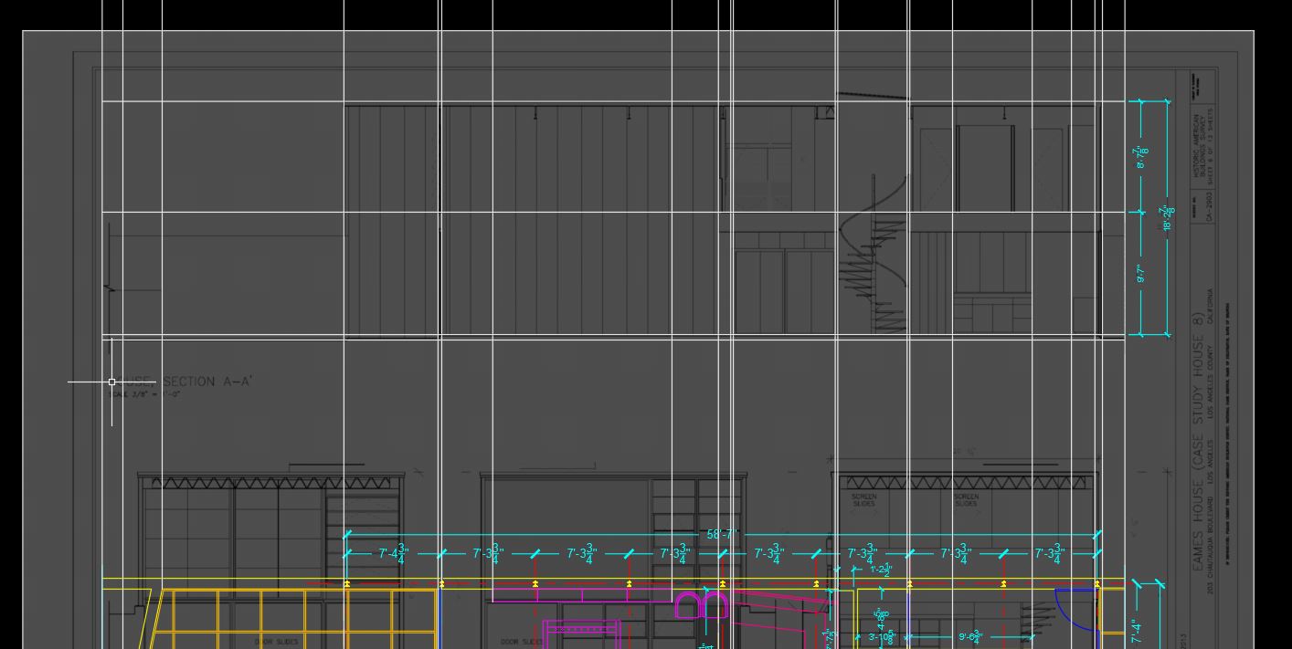
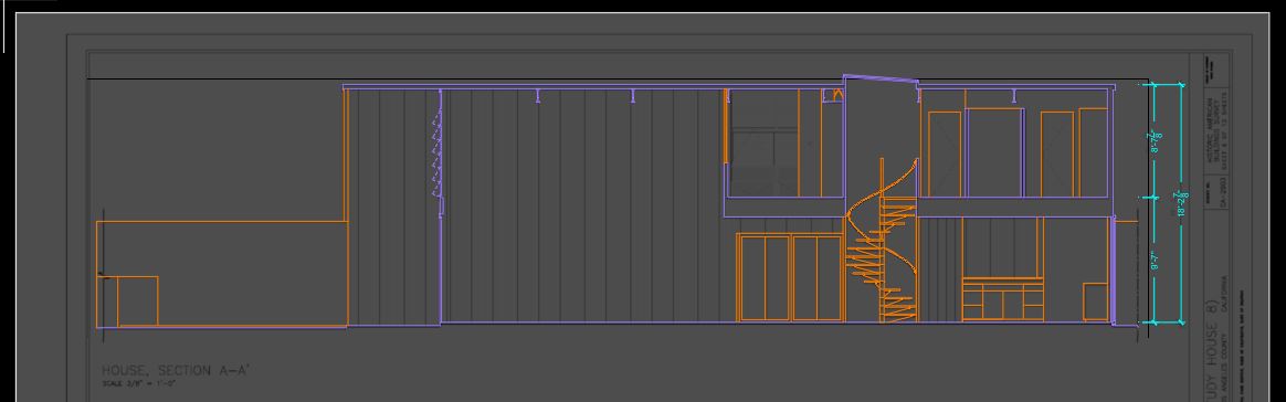
In this tutorial, students will draw a building section based on Eames House, House, Section A-A’ drawing, the plan south section (You can download the image from Canvas Module and this link Eames_House_House_Section_A-A’.jpg), and your space planning (Furnishings, fixtures, and equipment).
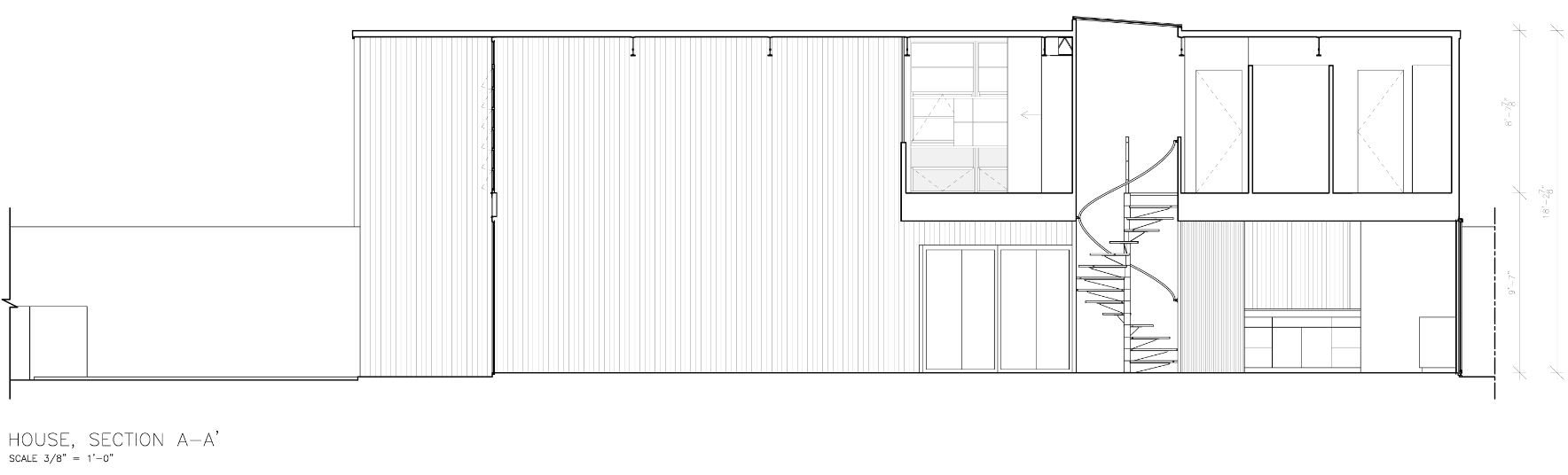
image credit: Screen captured by the Author from http://www.loc.gov/pictures/collection/hh/item/ca4169/ (Eames House as-built drawing, public domain)
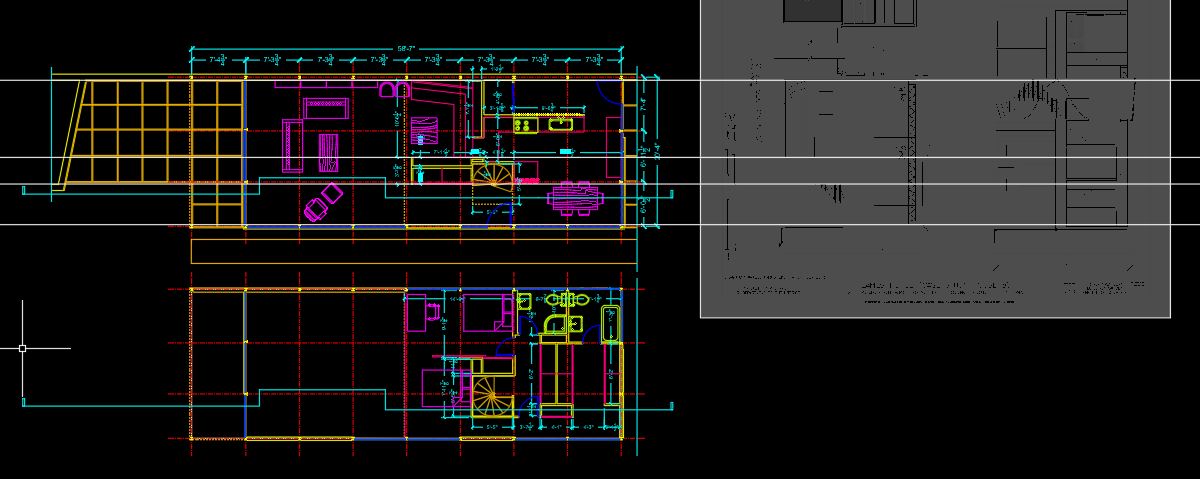
- [STEP 01] Open your CAD file for the Eames House Project.
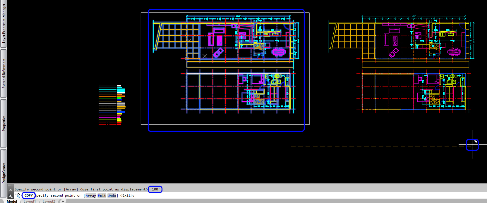
- [STEP 02] Copy the floor plans (1st floor & 2nd floor) to the right side 100′. This step is optional, but I prefer to save the original plans and to use the copied plans for creating a section view.
- [STEP 03] confirm you are in [0] layer and Draw a section line (recommended to use [PLINE]) on the first floor for a section view. Copy the section line in the same position for the second floor. You can rely on a column grid line. (For section line, you can break and offset the line to focus on key interior and/or architectural elements. The line should start and stop outside of the plan, and you should add a small perpendicular box to indicate the direction of the section view. Update the section lines to the [A-ANNO] layer.
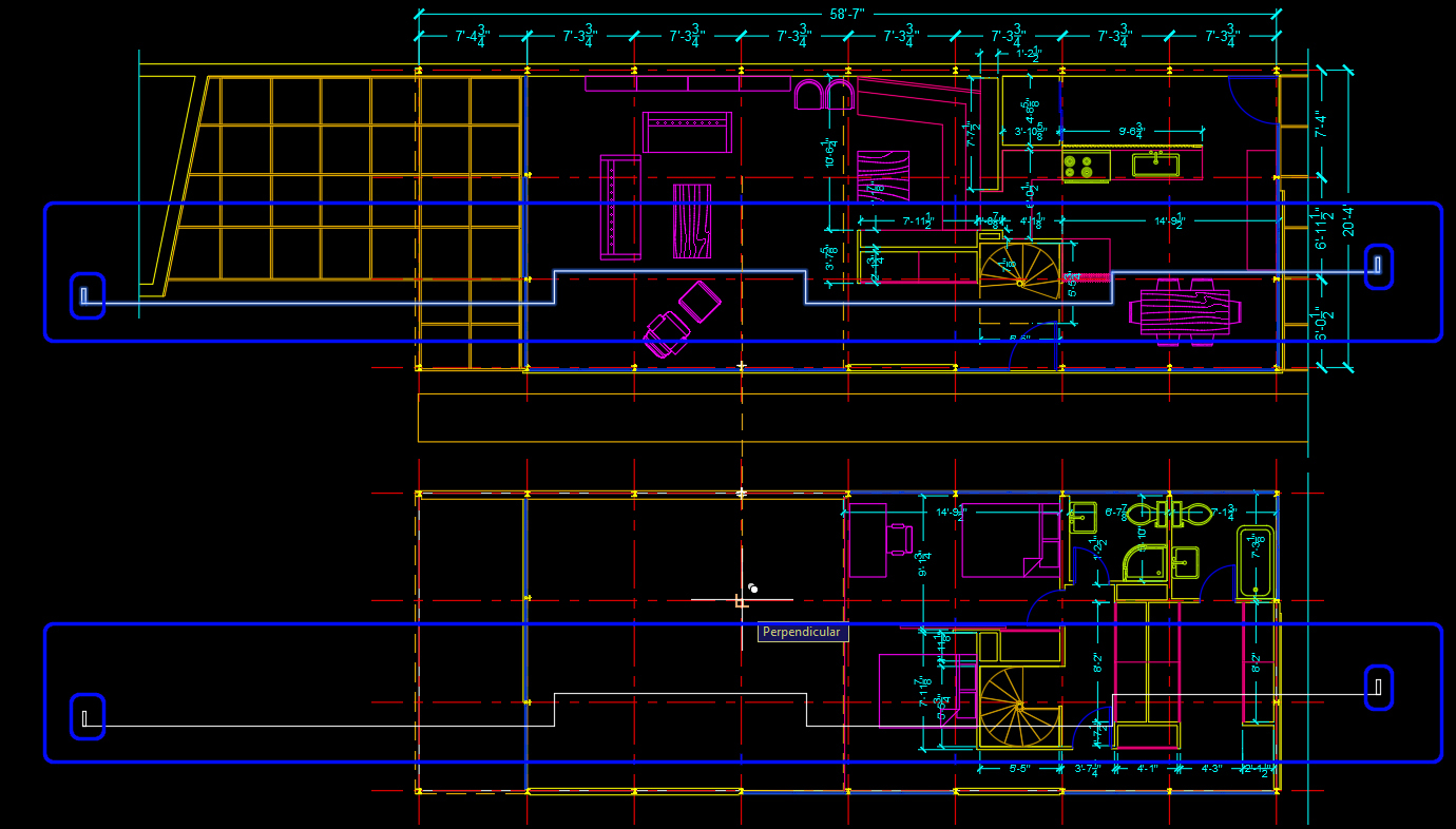
- [STEP 4] Draw a perpendicular line from the section line on the first floor to indicate the building boundary and drawing boundary.
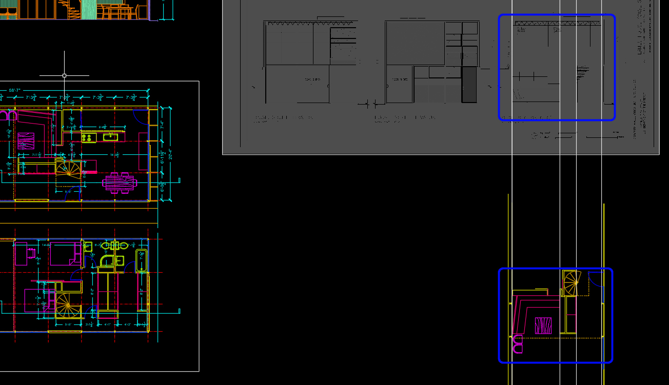
- [STEP 5] Insert the section drawing (Eames_House_House_Section_A-A’.jpg) by clicking [inset] > click [attach] > select the file Eames_House_House_Section_A-A’.jpg from your project folder > click [open] > click [ok] on Attach Image window > click a base point and the second point to insert the image > adjust Image Fade to 50 > mouse right-click on the image > click [Draw Order] > click [Send to Back]
- [STEP 6] Relocate (use [move] command) and rescale (use [scale] command) the inserted image to fit the building boundary for the section lines.
Note, you must use the object snape [F3] appropriately when you adjust the scale. Sometimes the object snap works perfectly to click the CAD object. Sometimes the command does not work to click a point in a raster image.
- [STEP 7] Now, you are ready to draw the section with the inserted image.
- Note 1. You will rely on the dimensions on the inserted image, the lines on your floor plan. Use numeric values to draw lines (please, don’t just click on the image except for the spiral stair. The image is reference only because the scaled image is always a bit off).
- Note 2. Create three new layers
- [A-LWT-OBJECT] 0.2mm – The edges of objects, and represent a change in depth
- [A-LWT-SECTION] 0.5mm – The lines are representing the boundary of anything cut-through
- [A-LWT-SURFACE] 0.05mm – The lines are detail lines on an object. They don’t represent much (if any) change in depth
- Note 3. Use [LINE]. [PLINE], [SPLINE], [CIRCLE], [TRIM], [OFFSET], [FILLET], [EXTEND], and [STRETCH] commands.
- Note 4. You also update the line type manually for door and window openings.
- Note 5. First, you draw the guidelines. You are using [xline] for creating a line of infinite length.
-
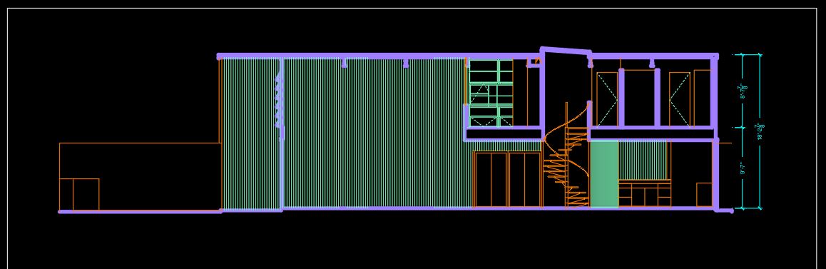
- Then, you draw the section lines.
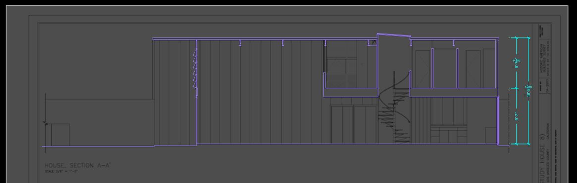
- Then, you draw the section lines.
-
- After that, you draw the object lines.
- After that, you draw the object lines.
-
- Draw surface lines for details.
- Draw surface lines for details.
-
- Finally, you add furniture, and you should edit the details and objects hidden from the front of the object.
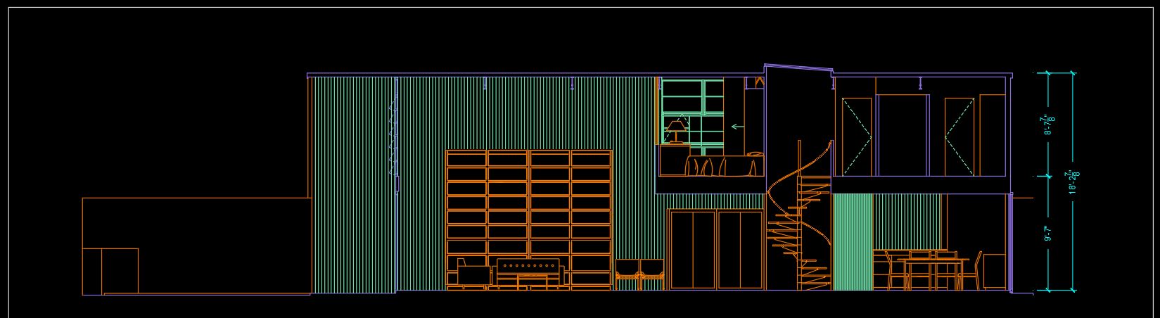
- Finally, you add furniture, and you should edit the details and objects hidden from the front of the object.
- [STEP 8] Move the section and the section lines that you drew except the inserted image 100′ to the left to save the section drawing in a safe drawing area.
- [STEP 9] Create a block for the section. Select all the elements in the section > Type [B] for creating a block > Define the name [000_Section A-A’] > Click [OK]
(CO 2) Draw an elevation from the floor plan
“An elevation is a view from the side of an object when drawing interior elevations; this would represent one of the walls. This would include any windows or doors as well as any built-in furniture that is in direct contact with the wall.”
Retrieved from https://www.nda.ac.uk/blog/identify-plans-elevations-sections/
“The term ‘elevation’ refers to an orthographic projection of the exterior (or sometimes the interior) faces of a building, that is, a two-dimensional drawing of the building’s façades.”
Retrieved from https://www.designingbuildings.co.uk/wiki/Elevations
In this tutorial, students will draw an interior elevation based on Eames House, House, Section C-C’ drawing, the plan west elevation in the living room. Students will not draw a section. You will need to understand the concept of elevation and will draw only interior elevation.
- [STEP 01] Decide an elevation view.
- [STEP 02] Draw outline of the elevation by using [xline] to draw the boundary of the elevation.
- [STEP 03] Rotate and relocate the section view c-c’ from the inserted image to match the boundary of the elevation. You will need to rotate 90degree clockwise.
- [STEP 04] Rotate the copied floor plan and the inserted image to 90degree counterclockwise. The reason for this step is to draw the elevation quickly. It typically takes less time to draw the elevation in the right direction (Up-North, Down-South, Left-West, and Right-East).
- [STEP 05] Remove the elements that are not needed from the copied floor plan. Make sure you saved the original floor plan. You only delete the elements in the COPIED floor plan.
- [STEP 06] Now you can draw the elevation
- Draw floor level and ceiling level (8′ -1″ AFF) (Typically, an interior elevation expresses interior elements only. You don’t draw wall thickness, window cut, ceiling structure, and roof structure.) > Change the lines for the wall ends, floor level, and the ceiling level to [A-LWT-SECTION]
- Switch the layer to [A-LWT-OBJECT] > Draw wall and furniture by using [LINE], [PLINE], [CIRCLE], [FILLET]. [TRIM]
- If needed, switch the layer to [A-LWT-SURFACE] > Draw anything that is not important in terms of construction.
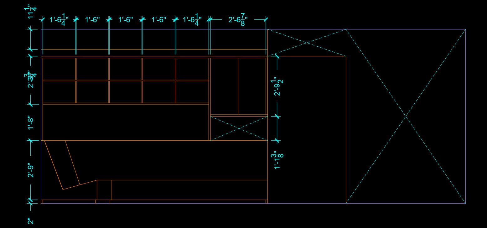
- [STEP 07] Add dimensions and opening for more information
- On the Application Status Bar, switch the scale to 3/8” = 1’ 0”
- Type [ddim] and press [enter] to open [Dimension Style Manger]
- Click [Annotative-3-32] > click [Set Current] > click [Close]
- Type [dim] and press [enter] to add dimension
- You will need to click the first extension line origin > click the second extension line origin > specify dimension line location. Repeat this process to add dimensions for the casework.
- [STEP 08] Make a block for the elevation.
- Select the elevation, including lines and dimensions.
- Type [b], press [enter] to open [Block Definition]
- Define the name [000_Elevation-A]
- Click [OK] to finish the command
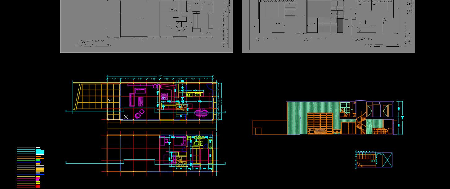
- [STEP 09] Organize your drawings.
- Move the inserted – reference images to 75′ plan north.
- Move your section and elevation on the right side of the floor plans.
(CO 3) Add/Edit Text & Annotation (in model space – annotative) – M Text, Text Style, M leader, and Multileader Style
In this tutorial, students will learn how to add and edit text and annotation in the drawing area by using [MULTILINE TEXT], [TEXTSTYLE], [MULTILINE LEADER], and [LEADERSTYLE]
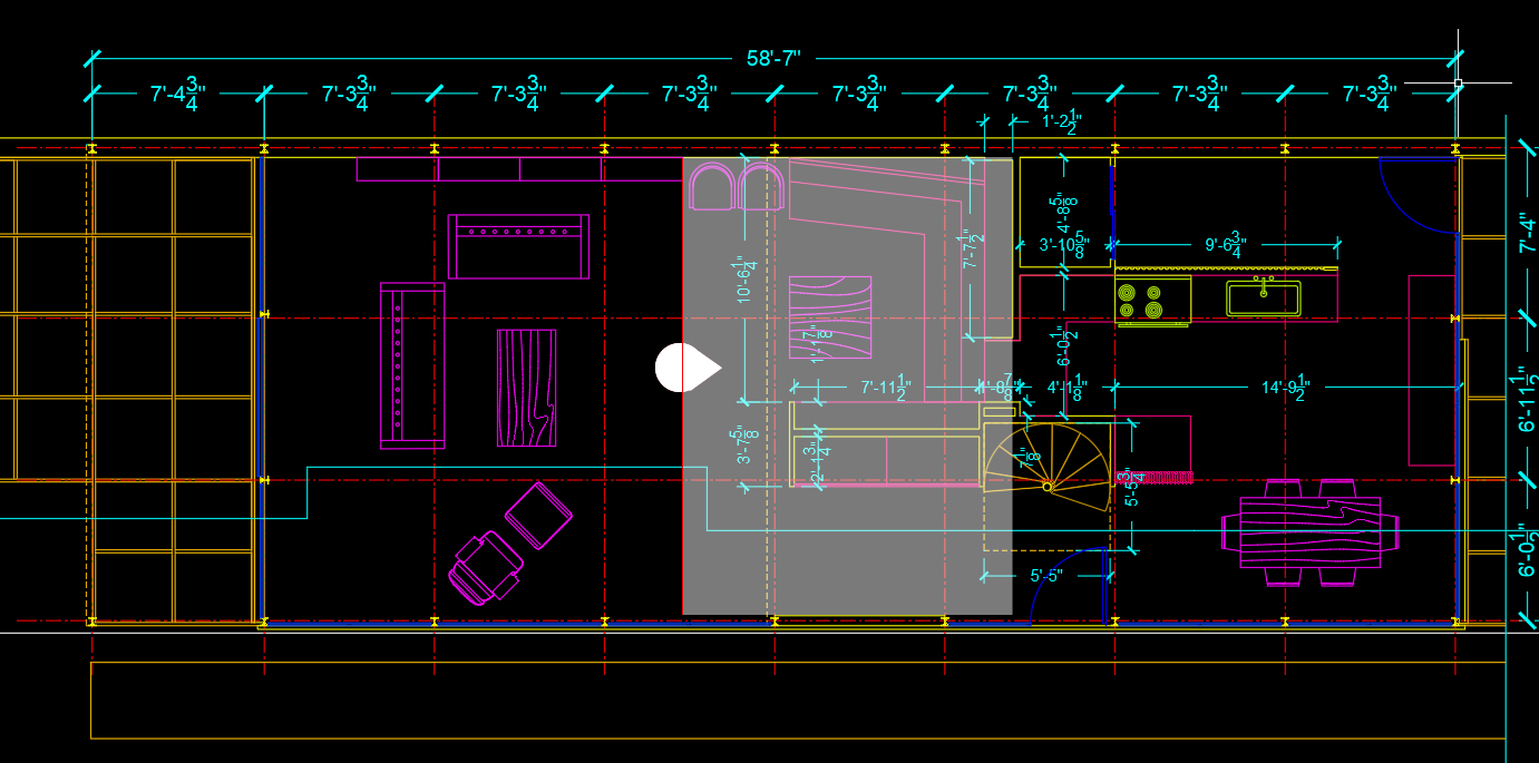
Add room names and room numbers on the floor plan.
- [STEP 01] Switch to the [A-ANNO-TEXT] layer
- [STEP 02] Adjust units by typing [UN] and press [enter] to open [Drawing units].
- The current unit precision is 0′ -0 1/16″
- Change the unit precision to 0′ -0 1/32″
- Click [OK] to close the Drawing units window
- [STEP 03] Add two text styles for the room names and room numbers
- From the Annotate tab, Text panel on the ribbon, Click [Standard] > Click [Manage Text Styles]
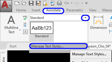
- From the Annotate tab, Text panel on the ribbon, Click [Standard] > Click [Manage Text Styles]
-
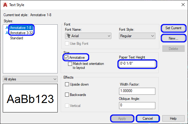
- On [Text Style] window, click [New]
- Enter Style name [Annotative 1-8] and click [OK]
- Confirm [Annotative] is checked, update Paper Text Height to [0′-0 1/8″]
- Click [Apply]
- Click [Set Current]
- Click [New]
- Enter Style name [Annotative 3-32] and click [OK]
- Confirm [Annotative] is checked, update Paper Text Height to [0′-0 3/32″]
- Click [Apply] and click [Close]
- [STEP 04] Add room name
- Verify the Text Style is [Annotative 1-8] from [Annotate] tab, on [Text] panel
- Click [Multiline Text] from [Annotate] tab, on [Text] panel
or, Type [mt] and press [Enter] - Define a text box for a room name. Using All Caps are recommended for a room name. Sometimes, use an acronym. (e.g., LIVING RM)
- Enter [a room name] and click a point outside of the text box.
- [STEP 05] Add room number
- Verify the Text Style is [Annotative 3-32] from [Annotate] tab, on [Text] panel
- Click [Multiline Text] from [Annotate] tab, on [Text] panel
or, Type [mt] and press [Enter] - Define a text box for a room number.
- Enter [a room name] and click a point outside of the text box. Typically, each room requires one number, e.g., 102 (The first number (1) indicates the floor number. In this case, the living room is located on the first level. The second and the third number (02) indicate room number that starts from the main entry to clockwise. In this case, the HALL is 101; LIVING RM is 102.
- Draw a box around using [RECTANGLE]
- [STEP 06] Create a block for the room name and number that you just created. Name the block to [000_Room name and number]
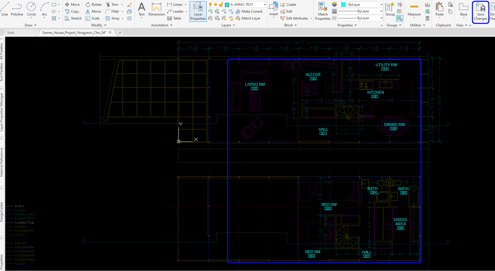
Note. This strategy is useful because once the block is updated on the floor plan, the room names and room numbers are automatically updated on other plans like a ceiling plan, finish plan and more. - [STEP 07] Use [Edit Block-in Place] to copy the room name and number to all rooms > Edit the names and numbers by double-clicking the name and the number > Click [Save Changes] to close [Edit Block-in Place]
- [STEP 08] Update the block from [A-ANNO-TEXT] layer to [0] layer
Add text and annotate on the floor plan
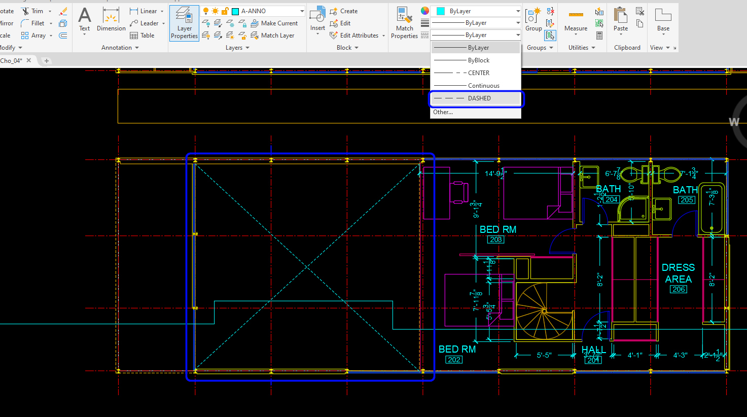
- [STEP 01] Switch to [A-ANNO] layer
- [STEP 02] Draw lines for openings and change [line type] to [Dashed]
- [STEP 03] Add multiline texts
- Add [OPEN TO BELOW] text on the second level above the LIVING RM-102. Make sure the scale is 3/16″ =1′ -0″ while you add the text
- Add [OPEN TO HALL] and [OPEN TO KITCHEN] texts on the [ELEVATION A]. Make sure the scale is 3/8″ =1′ -0″ while you add the text
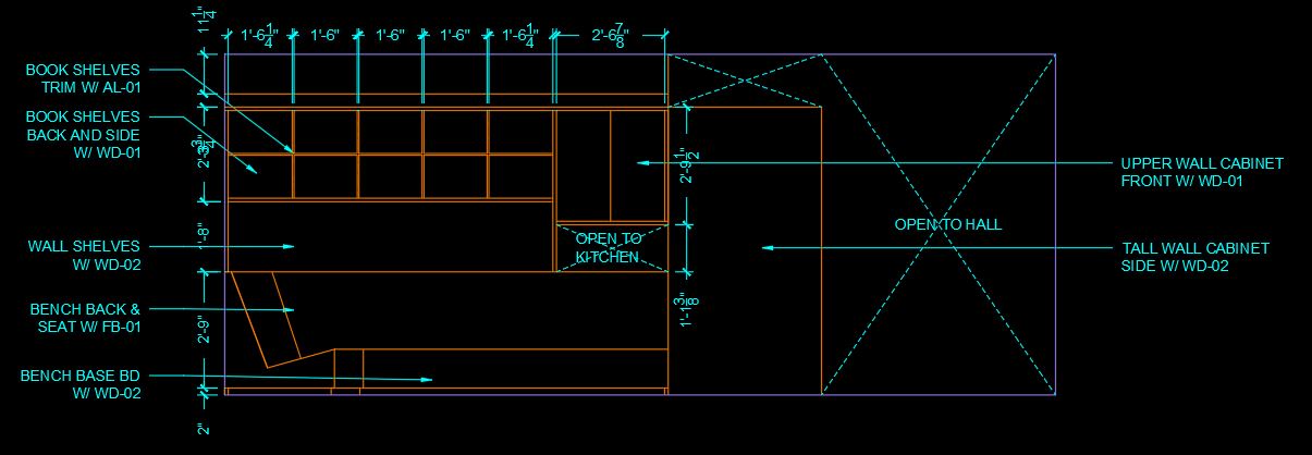
Add annotates on the elevation A
- [STEP 01] Switch to [A-ANNO-TEXT]
- [STEP 02] Click [Manage Multileader Styles] from Annotation tab, Leader panel, under Standard
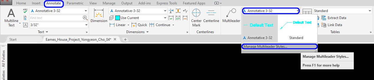
- [STEP 03] Click [NEW] > Add a new name for leader style [Annotative 3-32] > Check Annotative box on > Click [Continue]
- [STEP 04] Update these values to 3/32″ – Text height from Content tab, Landing gap from Content tab, Arrowhead size from Leader Format, Break size from Leader Format, and Set Landing distance from Leader Structure > Click [OK] to close the window
- [STEP 05] Click [Set Current]
- [STEP 06] Click [Multileader] from the Annotate tab, on the Leader panel
or, type [MLD] to add leader and text
SAVE the file before closing the application.
Save in a different location for the backup (e.g., a cloud folder)
 References
Designing Buildings Wiki. (2020, August 30). Elevations. Retrieved October 19, 2020, from https://www.designingbuildings.co.uk/wiki/Elevations
Designing Buildings Wiki. (2020, August 28). Section drawing. Retrieved October 19, 2020, from https://www.designingbuildings.co.uk/wiki/Section_drawing
Historic American Buildings Survey. (n.d.). Eames House, 203 Chautauqua Boulevard, Los Angeles, Los Angeles County, CA. Retrieved October 19, 2020, from http://www.loc.gov/pictures/collection/hh/item/ca4169/
National Design Academy. (2020, September 28). What’s the Difference Between a Plan, Elevation and a Section? Retrieved October 19, 2020, from https://www.nda.ac.uk/blog/identify-plans-elevations-sections/
