
Part Two. Revit
Chapter 11. Add/edit beams, walls, & curtain walls
Upon completing this session, students will be able to:
- (CO 1) Add/Edit Beam
- (CO 2) Create walls
- (CO 3) Edit walls wall properties – Wall thickness, Wall details, & Finishes
- (CO 4) Edit/add wall properties – Wall opening, wall sweep
- (CO 5) Add/Edit Curtainwalls, Mullions, & Panels
 Session Highlights
At the end of the session, students can create the graphics below.
 Lecture Contents
(CO 1) Add/Edit Beam
Adding beams are not typical for interior design projects, but it is needed for the Eames House project. You may use this information for an open ceiling plan of commercial projects as well.
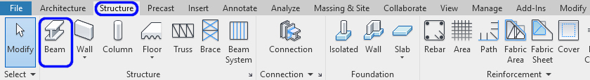
You can find [BEAM] from the [STRUCTURE] tab, under the [STRUCTURE] panel.
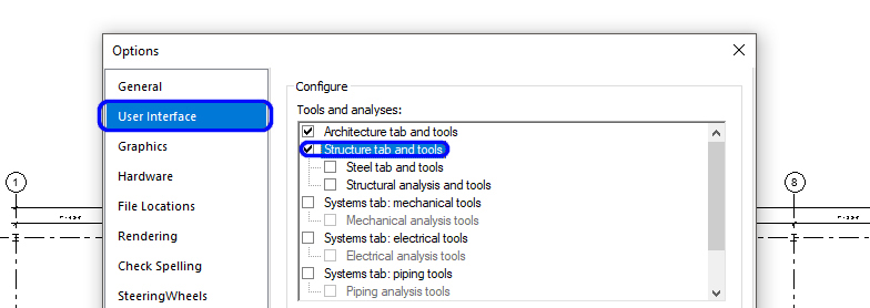
If you are missing the Structure tab, click [HOME] menu > Click [OPTION] > Click [USER INTERFACE] > Check [STRUCTURE TABL AND TOOLS]
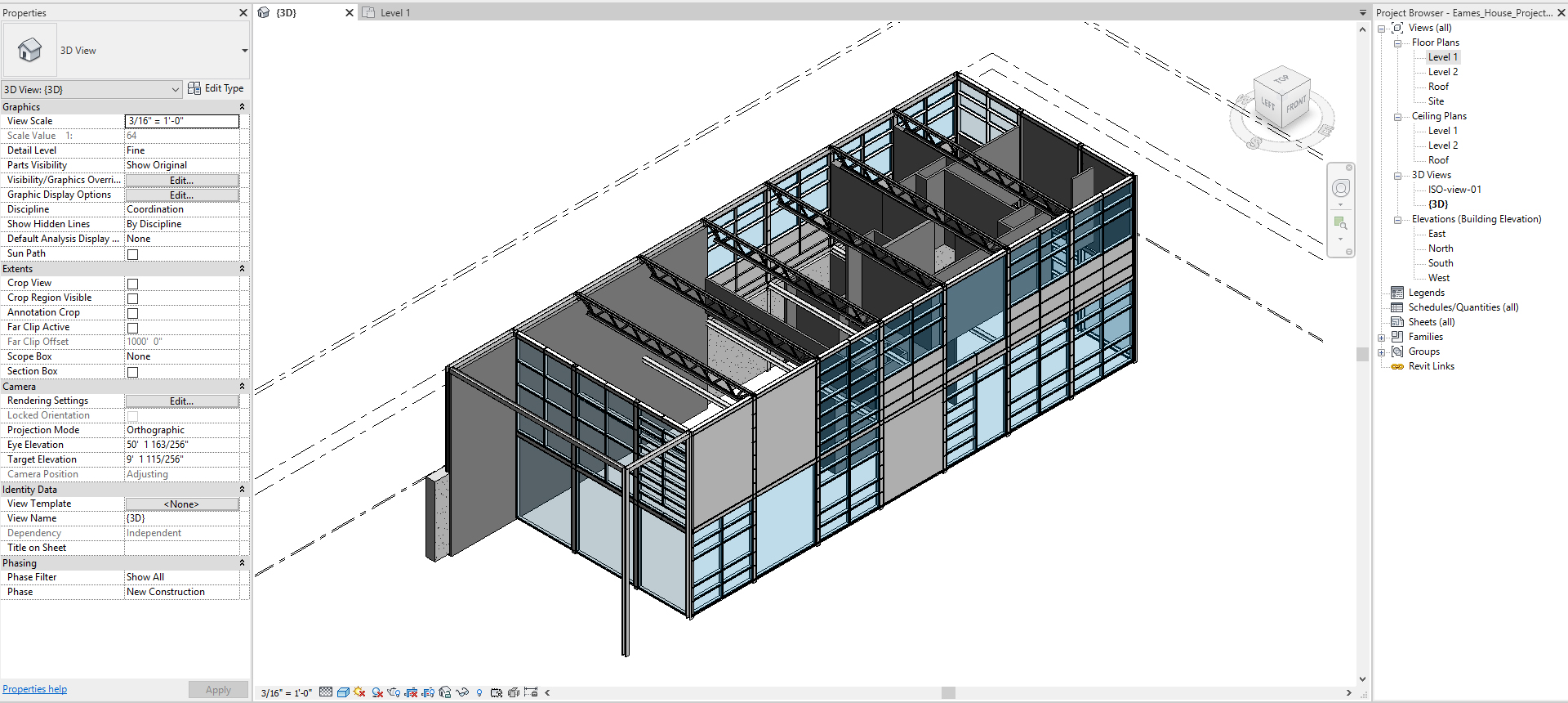
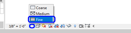
To see the structural element in solid shapes instead of lines, the view detail level must be [FINE]. Please update all floor plans, ceiling plans, and elevations to [FINE] on a detail level.
Add Beams
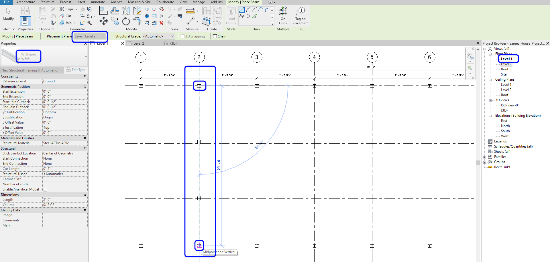
- [STEP 1] Click [Beam] on [Structure]
- [STEP 2] Select W Shapes-W5X5
- If you don’t have a W5x5 type. Please add one by clicking Edit Type > Duplicate > Name the type > Edit Width and Height to 5
- [STEP 3] Select [Level: Level 2] from Option Bar [Modify/Place Beam] for the West Wall of the building
- [STEP 4] Click the center of the north column of the west wall, and click the center of the south column of the west wall. You will get a warning message, but it is OK, just click X
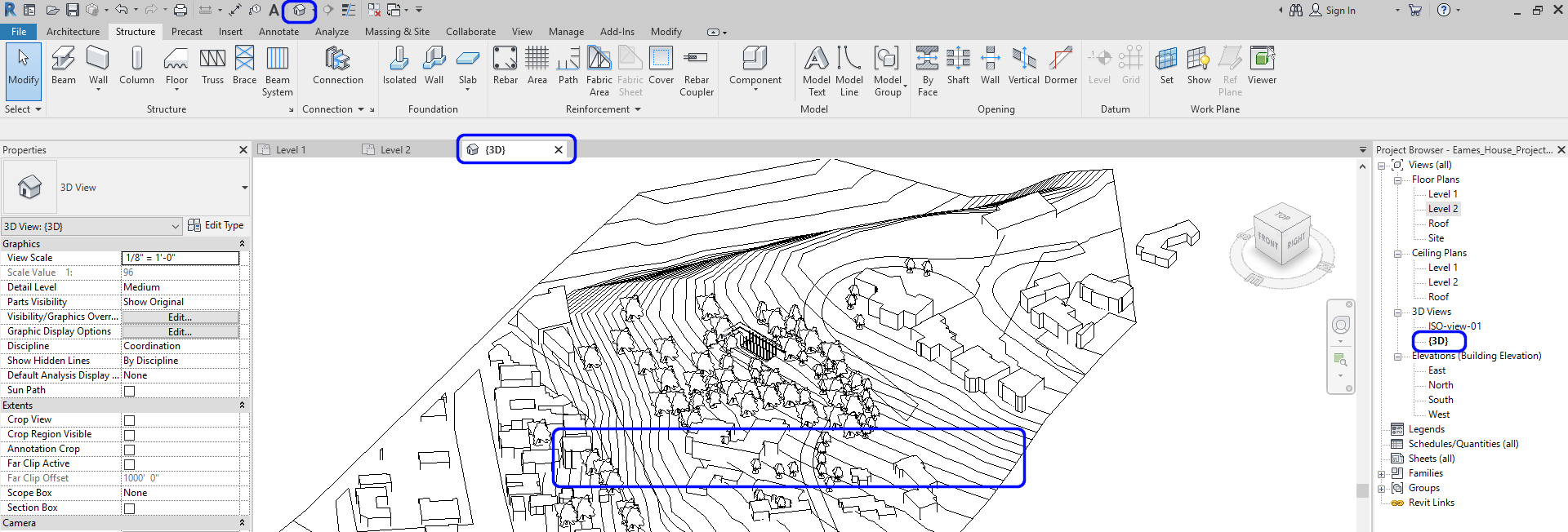
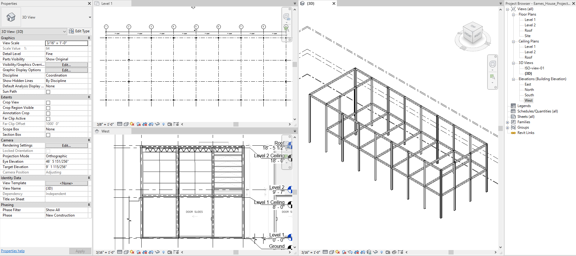
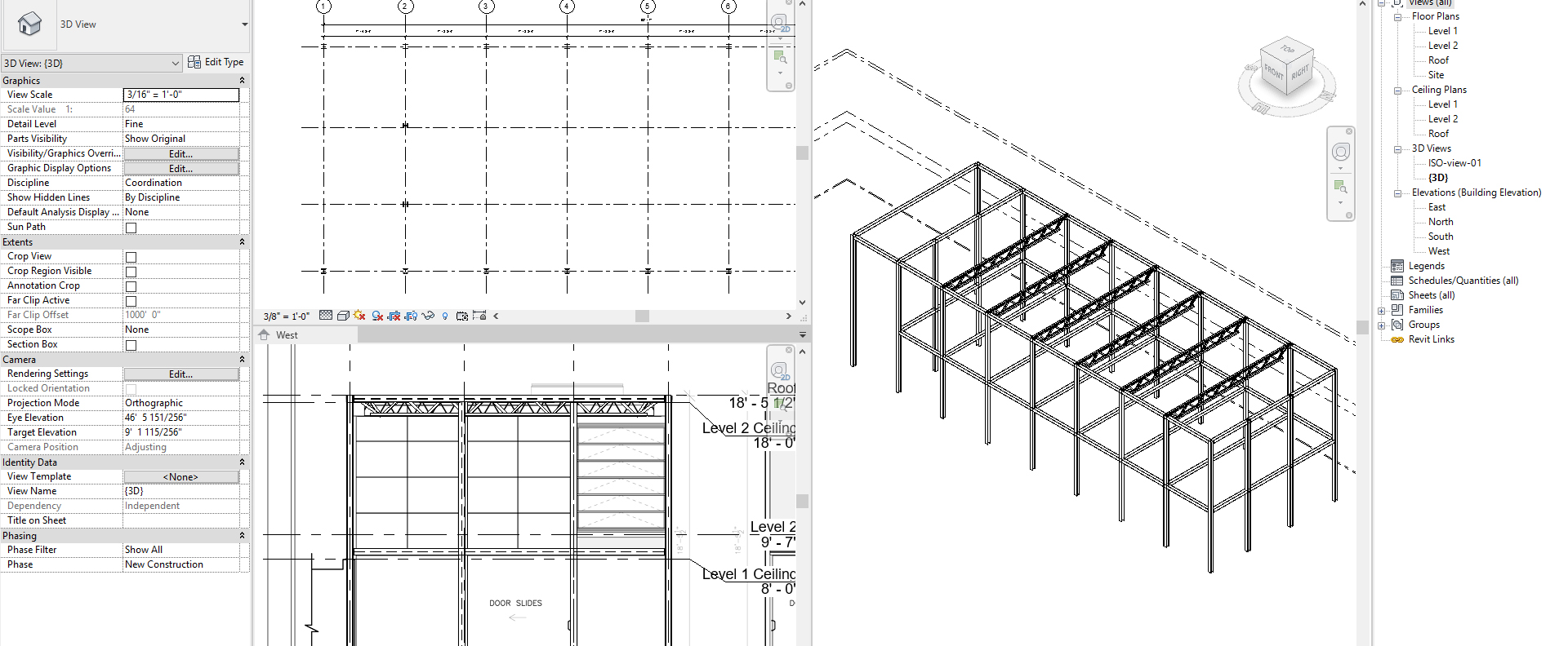
- [STEP 5] Confirm the place from the 3D view by clicking the HOUSE icon from quick access and hide site information by category. Update the 3D view scale to 3/8”=1’-0.”
- [STEP 6] Open the 3D view, West elevation, and the floor plan together by typing [WT]
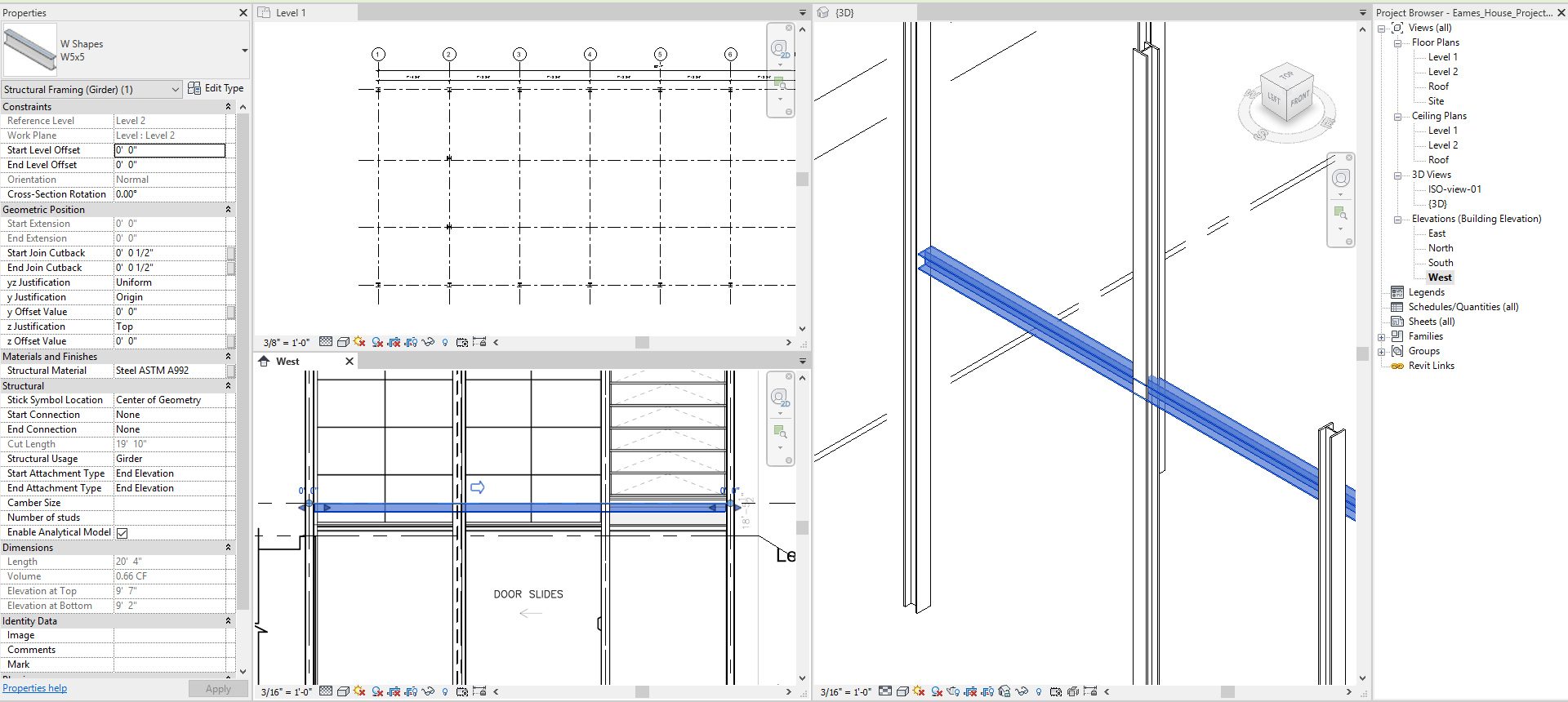
- [STEP 7] The Beam must be rotated to 90 degrees.
- Click the Beam, and change the properties
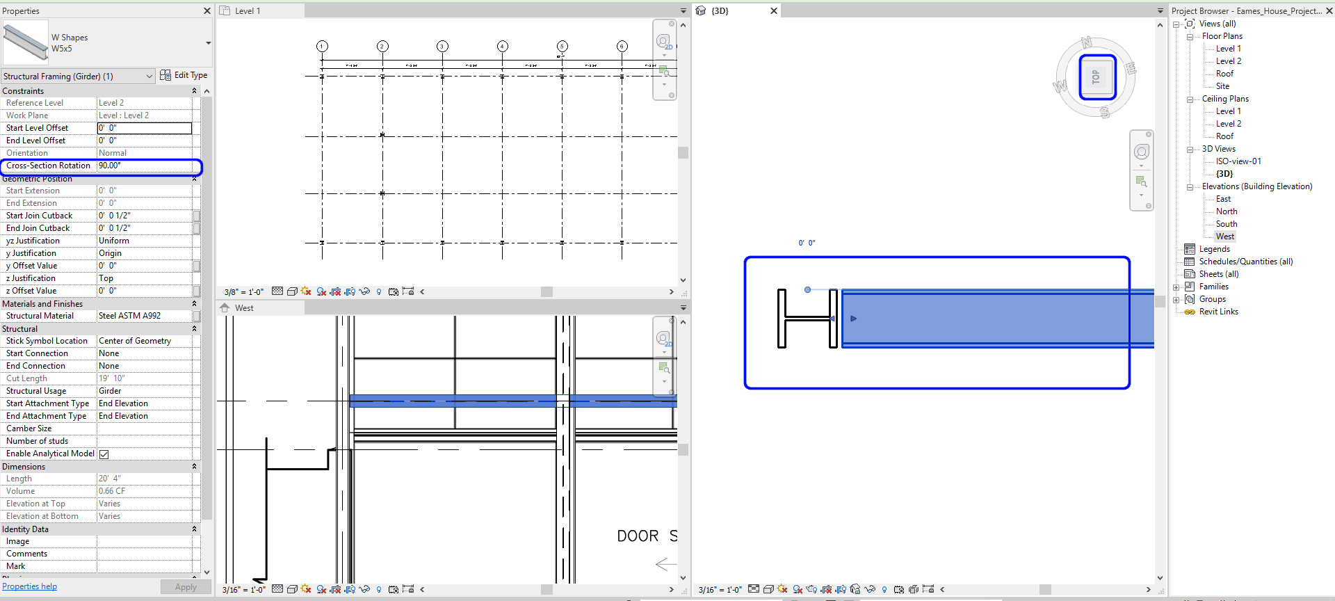
- Change Cross-Section Rotation to 90 degree
- The beam location needs to be aligned from the Top view of the 3D view. Use Move (MV) command to move the Beam to be aligned.
- [STEP 8] See the West elevation and move the Beam to align with the imported image, [MOVE] command will not work.
- Thus, update [Y OFFSET VALUE] to [1’ 1 ½”]
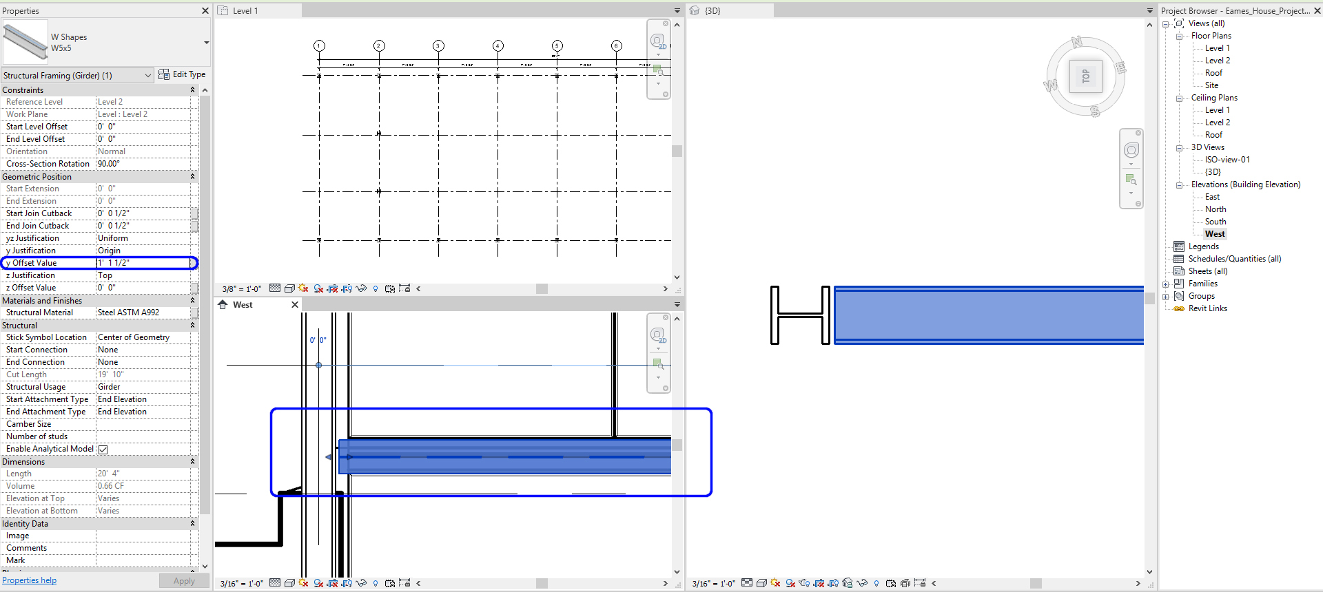
- Thus, update [Y OFFSET VALUE] to [1’ 1 ½”]
- [STEP 9] For other beams repeat step 1 through step 8. You may select all beams that you created and change the properties – Step 6 & 7. or Copy elements that have the same properties.
- Complete beams for the second floor and the roof exterior beams, AND the second level interior beams
- Complete beams for the second floor and the roof exterior beams, AND the second level interior beams
Add NEW Beams from a new family
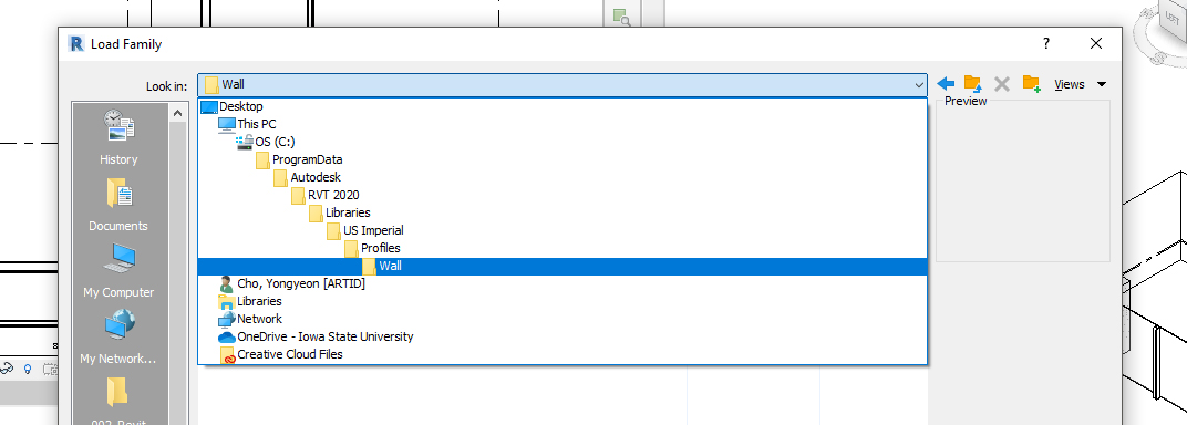
- [STEP 1] Click [Load Family] on [Insert] tab
- [STEP 2] Download [LH-Series Bar Joist.rfa] from Canvas Eames House module
- [STEP 3] Find the folder and select the file and Open
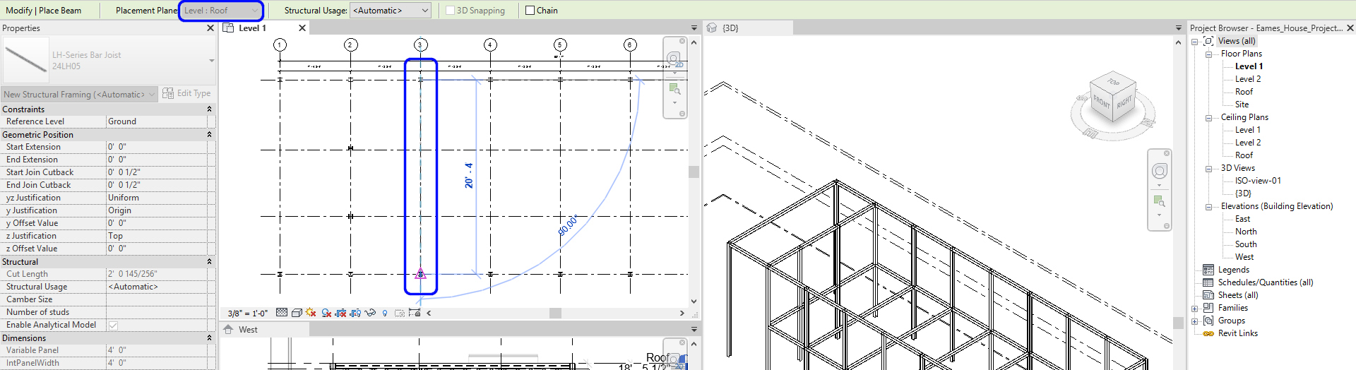
- [STEP 4] On Roof plan, Click [BEAM] on the [STRUCTURE] tab
- [STEP 5] Click North column and South column to create the Bar Joist
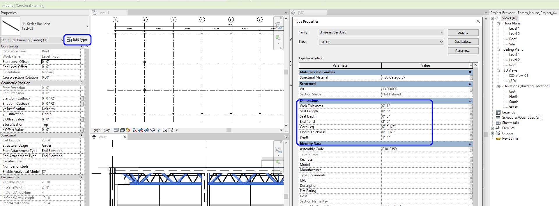
- [STEP 6] Edit the family type to match the imported drawing
- [STEP 7] Copy (CO) the first Bar Joist for the other Bar joists
(CO 2) Create walls
Draw WALLs with Various types based on the imported base drawing image
- [STEP 1] Select [WALL] from [ARCHITECTURE] tab, under [BUILD] panel
or Type [WA] - [STEP 2] Select a Wall family
- If you don’t have a wall type from the Properties, add by clicking Edit Type and Duplicate from a wall type.
- For Eames House, we will use
- Curtain Wall 1
- Retaining -12” Concrete
- Interior-4 7/8” Partition
- Interior-6 1/8” Partition
- Soffit-1/2” GWB & Metal Stud
- But the wall details will be modified, and custom walls will be added later in this tutorial.
- [STEP 3] Confirm [BASE CONSTRAINT] and [TOP CONSTANINT]. If needed set base offset and top offset
- [STEP 4] Specify Location Line
- [STEP 5] If the wall is other than a straight line, specify a line/shape type (circle, arc, rectangle, inscribed polygon, or ellipse. And draw lines to cross-reference of the imported base drawing image
- [STEP 6] Make Dimensions [DI] for verification purposes.
- [STEP 7] Confirm with 3D view
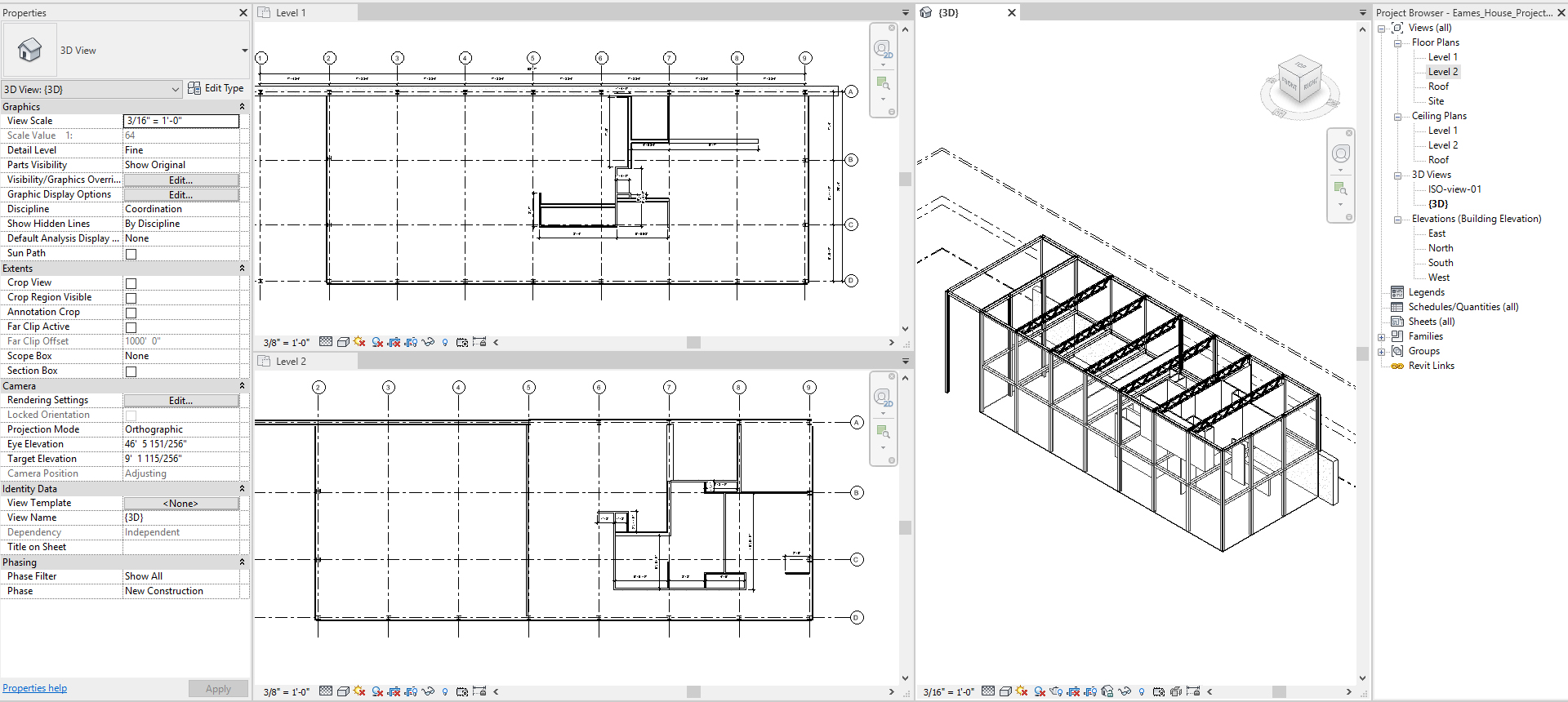
(CO 3) Edit walls wall properties – Wall thickness, Wall details, & Finishes
For your wall thickness, refer to Kilmer, W., & Kilmer, Rosemary. (2016). Construction drawings and details / W. Otie Kilmer and Rosemary Kilmer. (Third ed.).
For your design project, you will need to decide on your construction details.
Typical residential house wall thickness (For your reference)
- Interior Wall (without Plumbing) = 4 ½” ((1) 2”X4” wood stud, which are 3 ½” deep + (2) ½” Gypsum boards)
- Interior Wall (with Plumbing) = 6 ½” ((1) 2”X6” wood stud, which are 5 ½” deep + (2) ½” Gypsum boards)
- Exterior Wall (with Brick) = 10” ((1) 2”X6” wood stud, which are 5 ½” deep + (1) ½” Gypsum boards + (1) ½” Insulation + (1) 3 ½” Brick)
- Exterior Wall (with Stucco, wood, aluminum, or vinyl) = 7 1/2” ((1) 2”X6” wood stud, which are 5 ½” deep + (1) ½” Gypsum boards + (1) ½” Insulation + (1) 1” Stucco, wood, aluminum, or vinyl)
For the Eames house project, although this building is residential, the construction is a combination of wood base and metal base. Revit provides walls for commercial construction, which is a metal base, so, you may use the provided walls and change some walls.
- Interior Wall = Wood stud with Gypsum BD + Paint Finish or Wood BD (3 1/8”, 4 7/8”, 6”, 8”)
- Exterior Wall = Curtain Wall with Glass, Wood, Metal panels
- Exterior Wall = Metal with Gypsum BD + Paint Finish or Wood BD
- Exterior Retain Wall = Concert
Once you click a wall, you can edit the properties (wall height-where it starts and ends & wall phase) for each wall
If you want to change the wall’s type (wall thickness Graphic style, materials, Structure, BIM information), you can change by clicking [Edit Type]
For the future strategy, it is wise to [Duplicate] the type and edit type properties. For best practice, add “000” for the new duplication. This will allow the types to organize in alphabetical order.
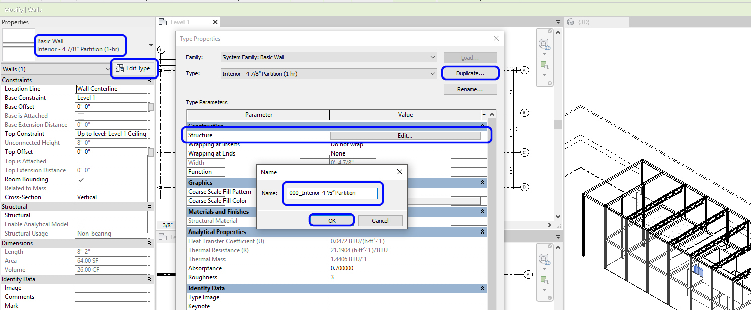
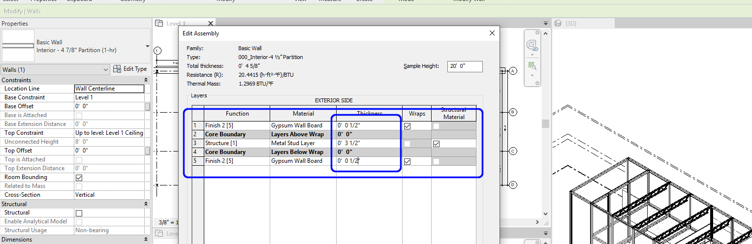
Click [EDIT] on [STRUCTURE] and change thickness and material and click [OK]
To change other walls from the Revit Metal base 4 7/8” wall to Wood base 4 ½.”
- [STEP 1] Click one of Metal base 4 7/8” wall
- [STEP 2] Mouse right click and click [Select all instances] and click [in Entire Project]
- [STEP 3] Select [000_Interior-4 ½” Partition]
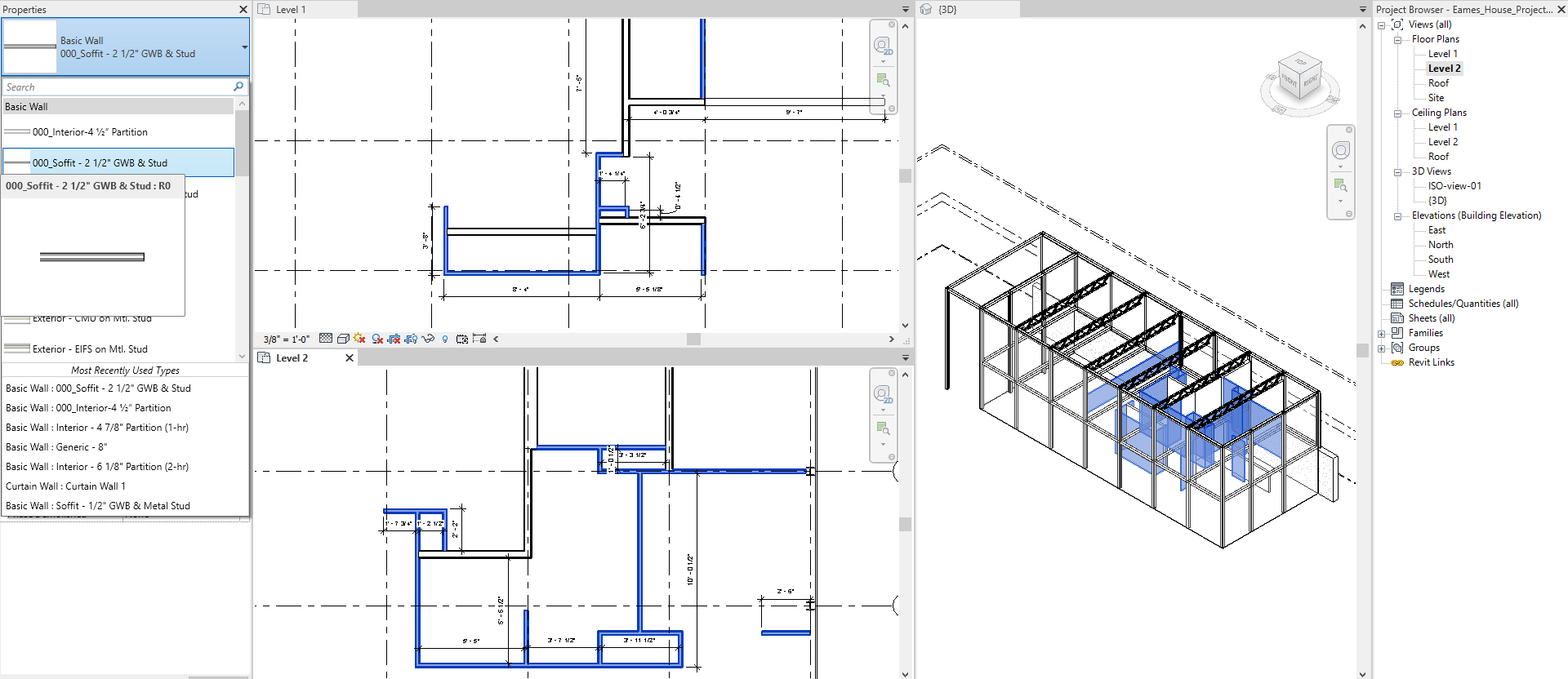
(CO 4) Edit/add wall properties – Wall opening, wall sweep
Wall opening or wall elevation modification
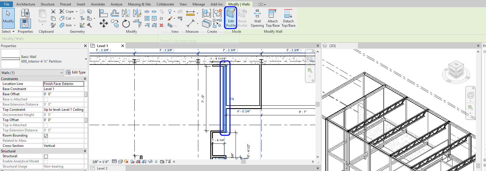
- [STEP 1] On a plan view, click the wall that you want to make wall opening
- [STEP 2] Click [Edit Profile]
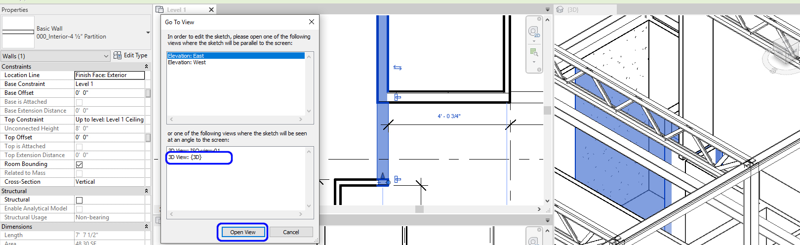
- [STEP 3] Go To View window will open.
- [STEP 4] Select an appropriate view to open. I prefer the ISO view to quickly change the elements
- [STEP 5] Draw the opening with dimension
- [STEP 6] Click the green checkmark to finish
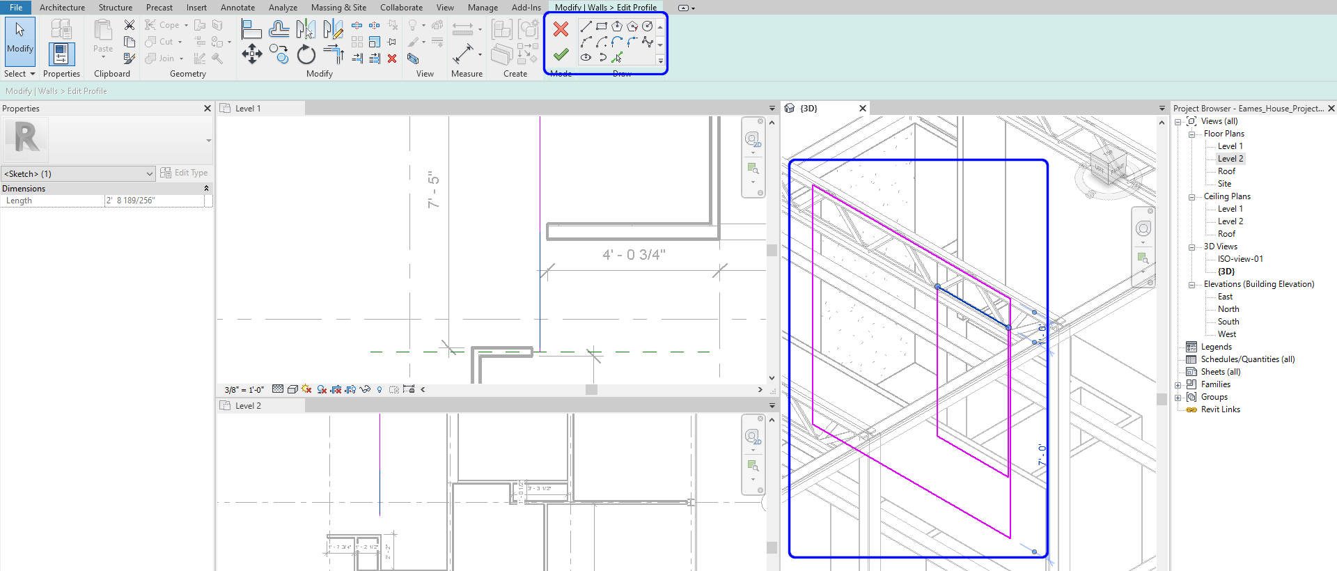
- [STEP 7] Double check in 3D view
Wall Sweep is a very useful tool to create moldings
- [STEP 1] To create a continuous molding. First, you need to load a profile by clicking [Load Family] from the [Insert] tab.
- [STEP 2] Find Profile from Revit library and open it to the file.
- [STEP 3] Click the small arrow under Wall on Architecture tab
- [STEP 4] Select Wall: Sweep on 3D view. Recommend a camera view or a 3D view with a section box
- [STEP 5] Click [Edit Type] > Duplicate the type. Don’t forget to add “000” for your type.
- [STEP 6] Click profile under construction, select the profile you just loaded.
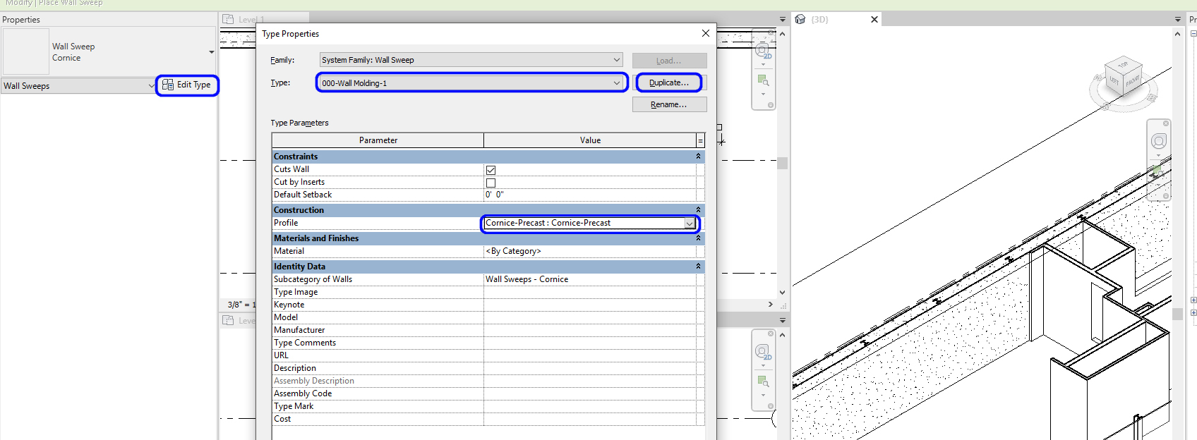
- [STEP 7] See the preview and click the appropriate location on the wall for the molding on the 3D view.
- [STEP 8] To finish the Sweep, [ESC] on Keyboard.
(CO 5) Add/Edit Curtainwalls, Mullions, & Panels
Modify curtain wall
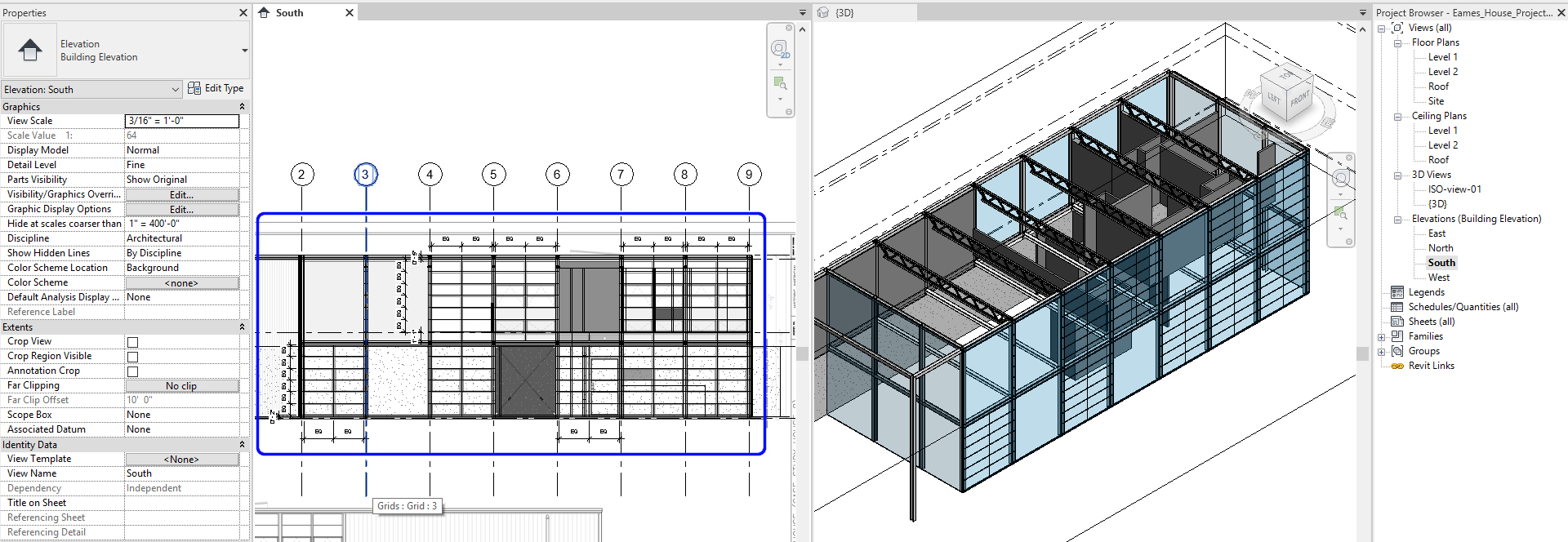
- [STEP 1] To add curtain wall grids, open a view. It can be an elevation view. You may close the floor plans.
- [STEP 2] For the Eames house project, confirm the imported base drawing – elevations are in the correct locations.
- [STEP 3] Click [Curtain Grid] on [Architecture] tab
- [STEP 4] Select [All Segments] or [One segment]
- [STEP 5] Click grid lines and use dimensions for accurate distance based on the imported elevations
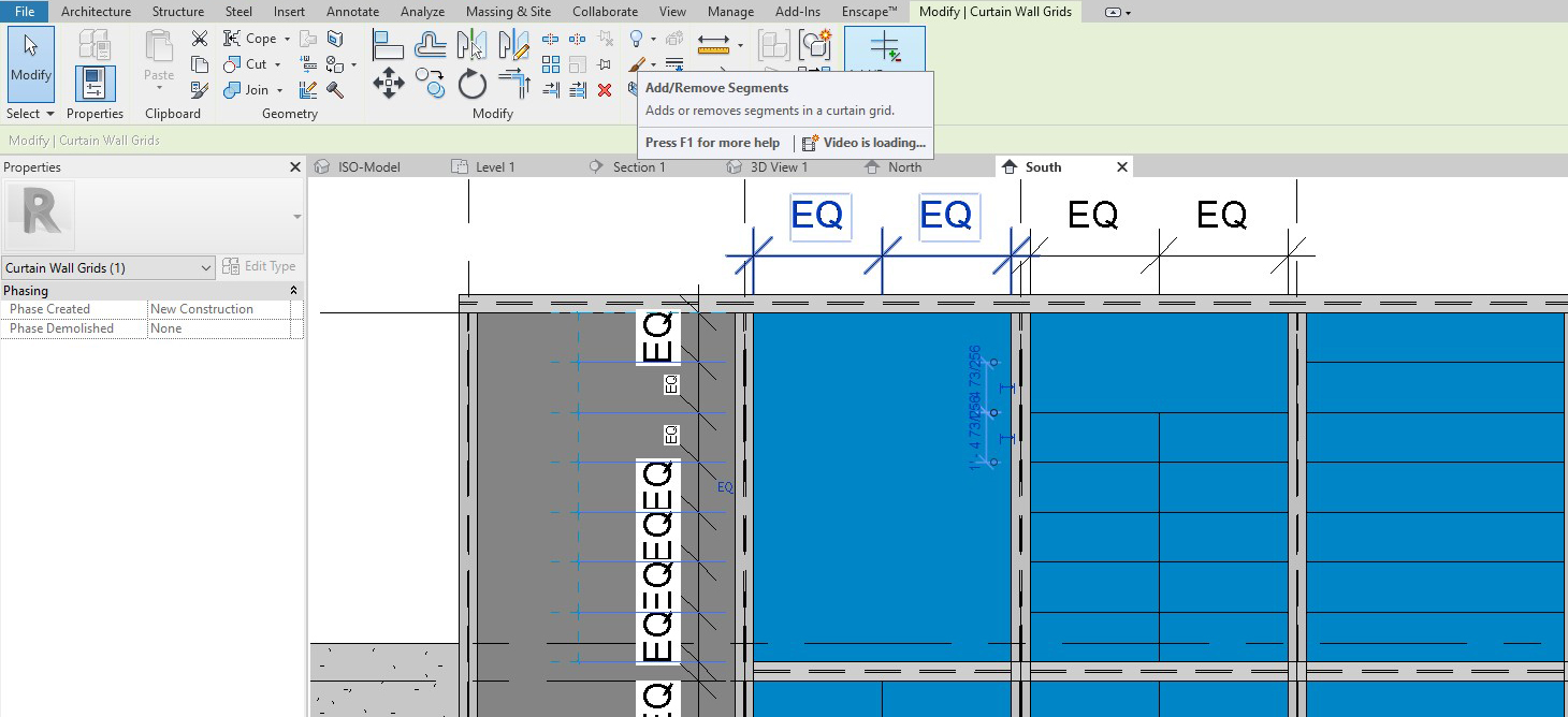
- [STEP 6] You can edit the grid, click the grid, and click add/remove segments.
- Complete for all four exterior walls
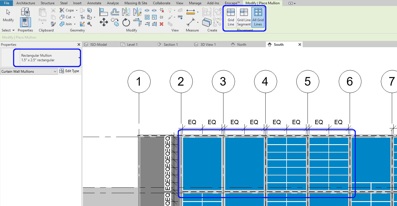
Add curtain wall mullion
- [STEP 1] On the elevation, click [MULLION] on the [ARCHITECTURE] tab
- [STEP 2] You may choose All Grid Lines, Grid Line, or Grid Line Segment
- [STEP 3] Also, you may choose a specific type of Mullion by clicking Properties, and you can edit the type as well
- You can change material, size, profile, the width of sides, angle, & offset
- [STEP 4] Click lines to apply the mullion type that you selected
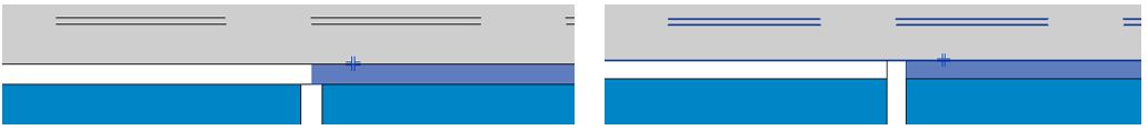
Modify Mullion
- [STEP 1] If you need to change the mullion type, you can click the mullion that you made and change the properties
- [STEP 2] If you need to change the mullion type and join order, click the Mullion you want to change and click [+] on the view to change the order
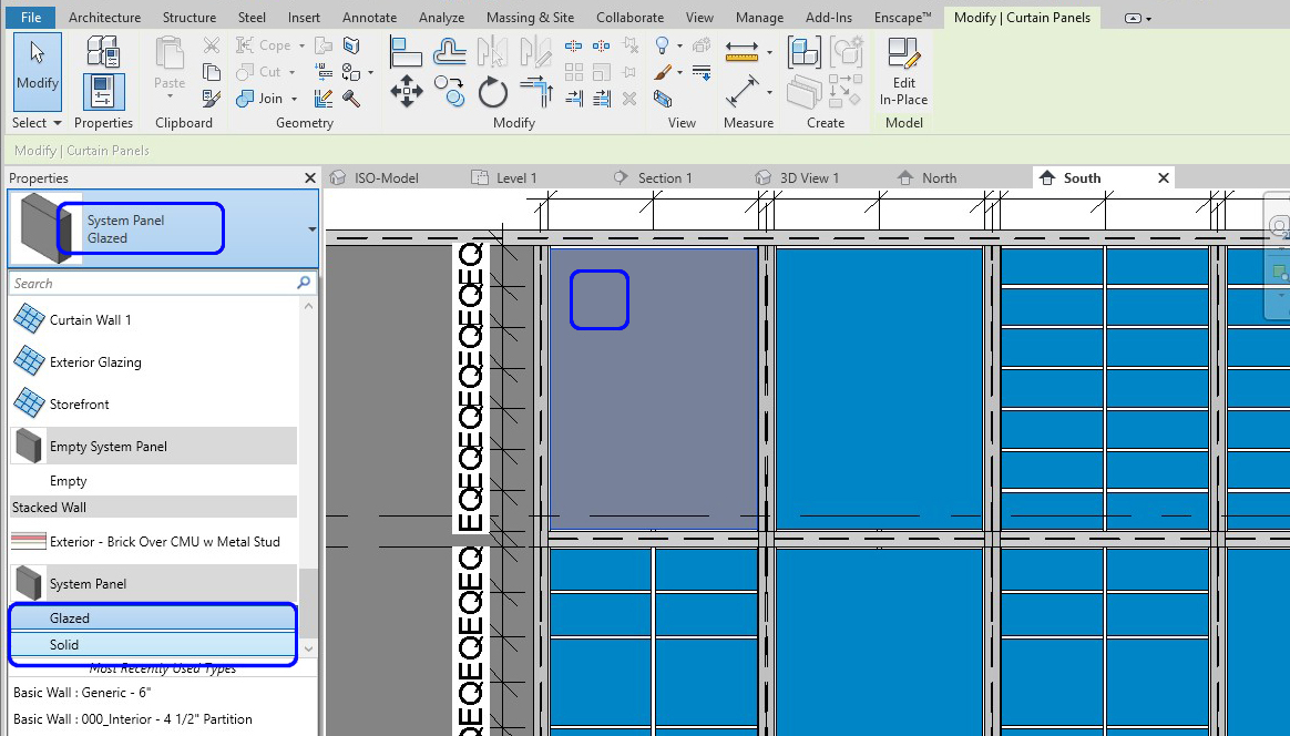
To change the panel from Glazing to Solid, door, or window
- [STEP 1] Select the panel to change by multiple [Tab] keys
- [STEP 2] Change Properties to what you need
- [STEP 3] If you need to change the properties, click [Edit type] and click [Duplicate] and change the value
- [STEP 4] If you need to add a new type, Load family first and change the Properties
SAVE the file before closing the application.
Save in a different location for the backup (e.g., a cloud folder)
