
Part One. AutoCAD
Chapter 5. Draw ceiling plans
- (CO 1) Draw RCPs from Floor plans
- (CO 2) Add/Edit Hatch
- (CO 3) Create a legend for the RCPs
 Session Highlights
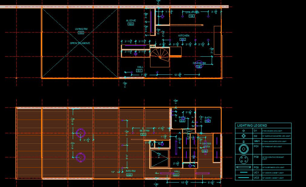
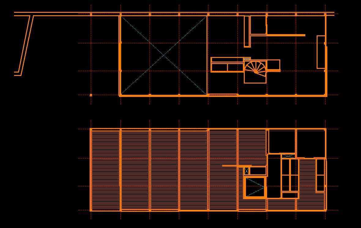
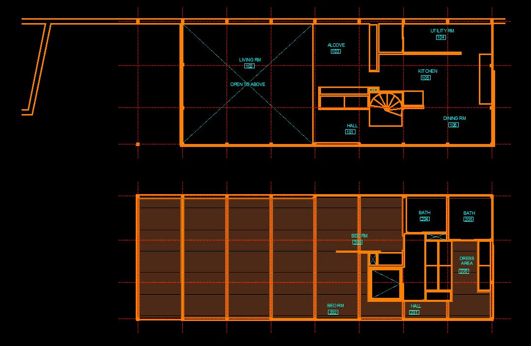
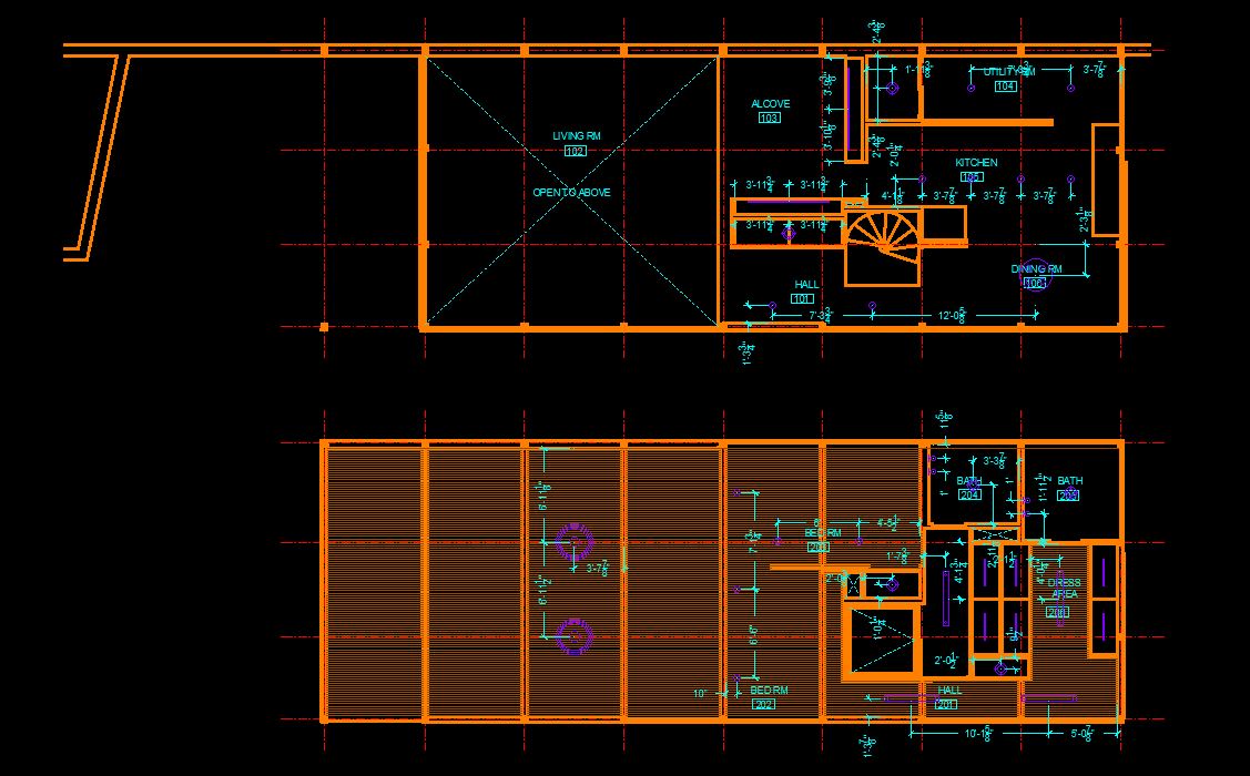
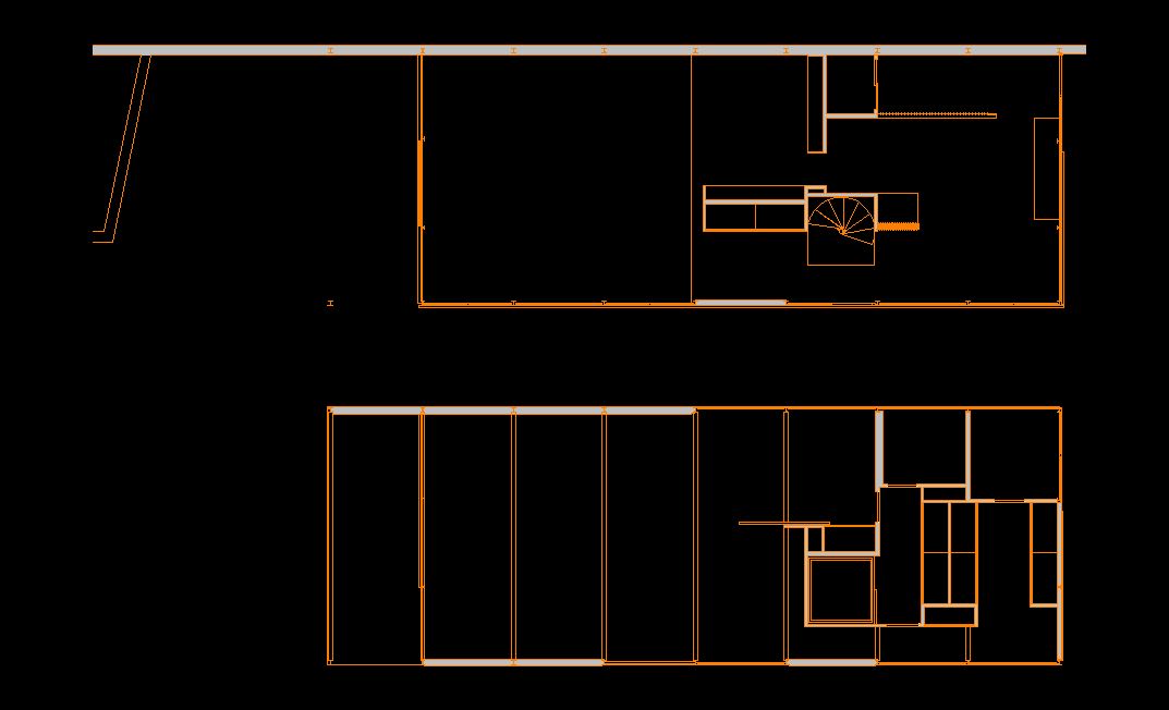
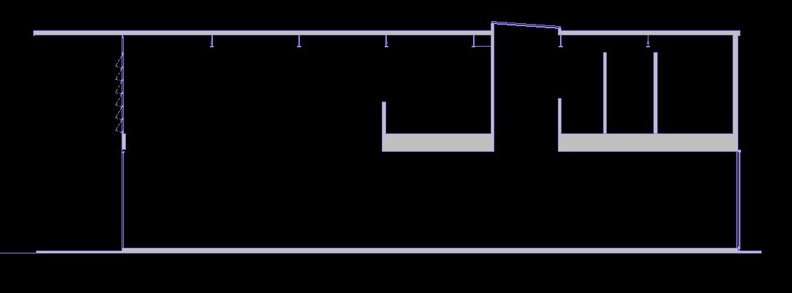
At the end of the session, students can create the graphics below.
 Lecture Contents
(CO 1) Draw Reflected ceiling plans (RCPs) from floor plans
In this tutorial, you will learn how to draw an RCP in AutoCAD.
Open your AutoCAD file
Copy elements from the floor plan
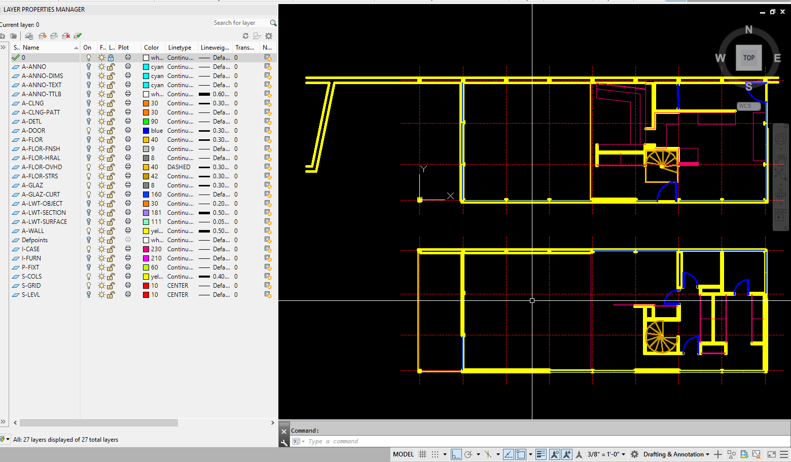
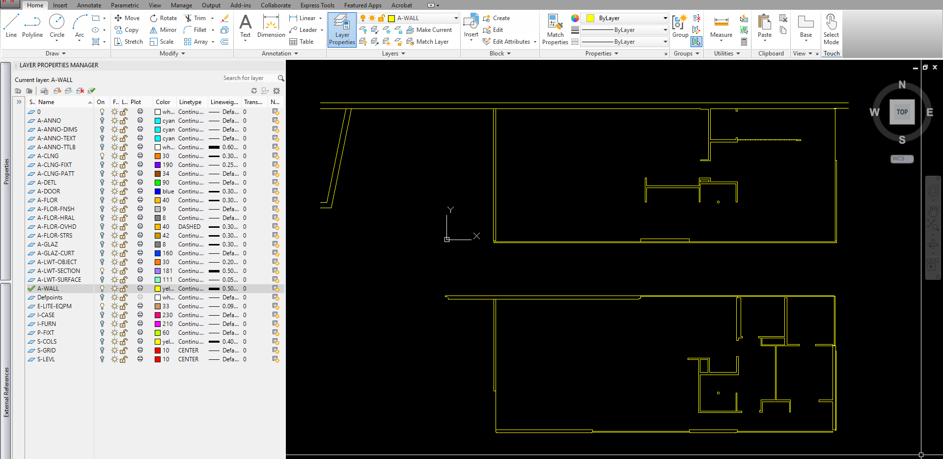
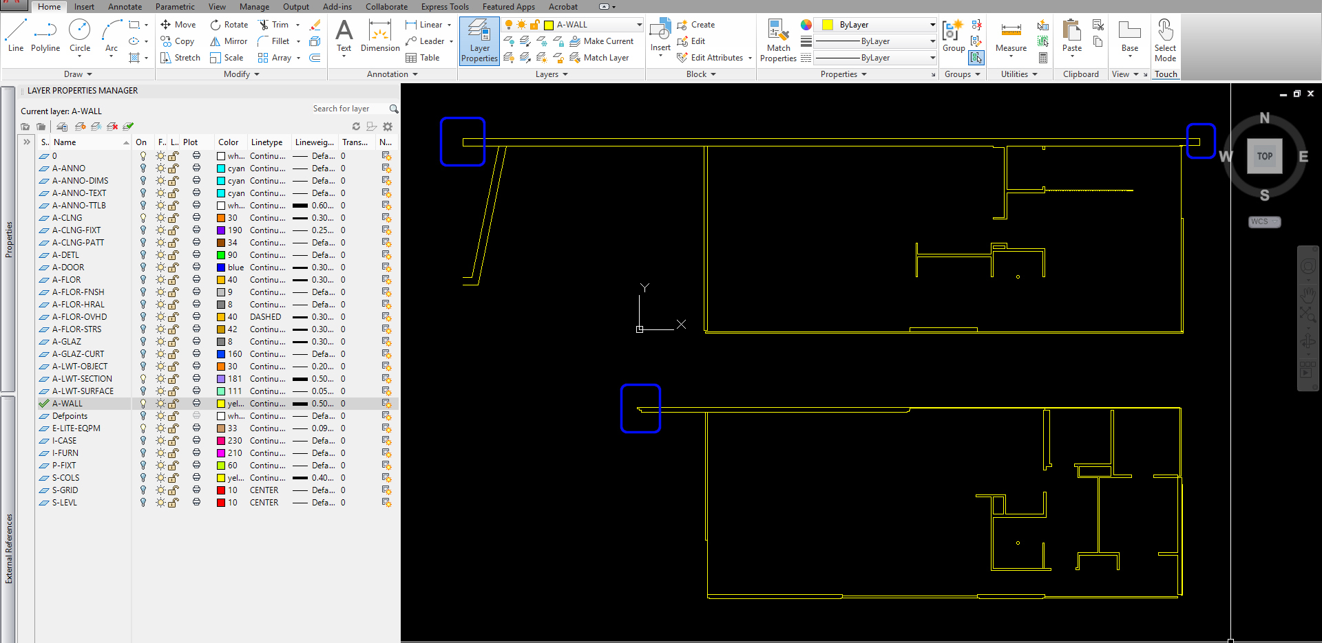
- [STEP 01] Turn layers off that are not needed to copy for the RCPs.
Turn off the following layers: A-ANNO, A-ANNO-DIMS, A-ANNO-TEXT, ANNO-TTLB, A-CLNG, A-CLNG-PATT, A-DETL, A-FLOR, A-FLOR-FNSH, A-FLOR-HRAL, A-LWT-OBJECT, A-LWT-SECTION, A-LWT-SURFACE, Defpoints, I-FURN, P-FIX, S-LEVEL
- [STEP 02] Copy the remaining elements to 100’ plan south direction
- [STEP 03] Turn on all layers
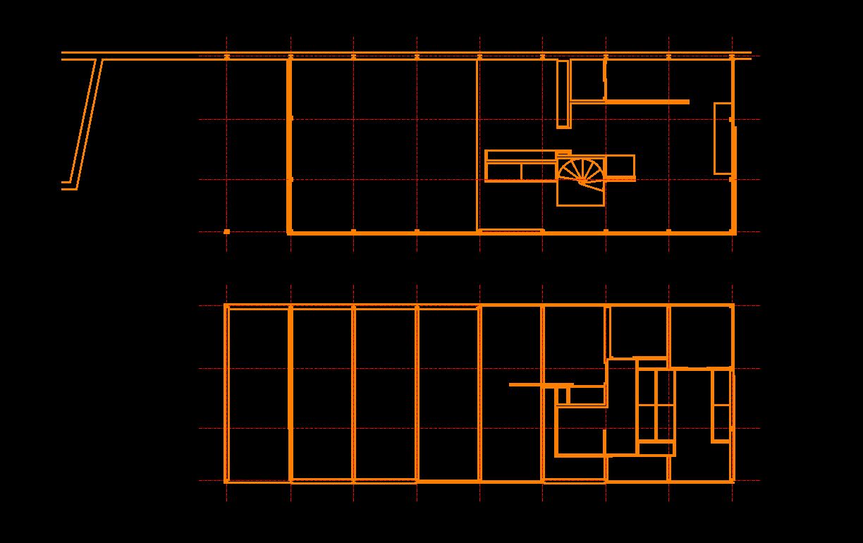
- [STEP 04] Clean up the plan
- In the space, we want to show all door openings, but not the doors themselves. To remove the door swing, you must Explode the door blocks and remove the doors themselves and swings
- For the casework, remove the casework that is not below 5 ft.
- Extend lines as needed to clean up the plan
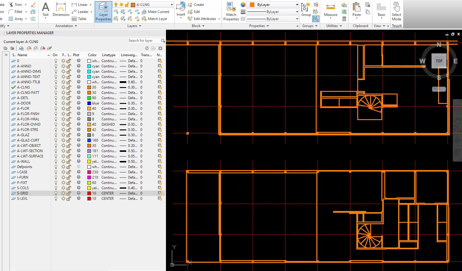
- [STEP 05] Lock [S-GRID] layer > Select all walls and elements for the RCPs > Switch to the [A-CLNG] layer.
- [STEP 06] Make the [A-CLNG] layer to the Current Layer
- [STEP 07] Add ceiling elements (height changes and ceiling structure if it is the open ceiling)
- [STEP 08] Make the [A-CLNG-PATT] layer to the Current Layer > Confirm the layer color to 34 > Add ceiling pattern
- [STEP 09] Make the [A-CLNG-PATT] layer to the Current Layer > Add ceiling annotation
- [STEP 10] Copy the room name and number block from floor plan
- [STEP 11] Create Lighting symbols
- You can bring lighting symbols (blocks) from other websites or the samples from Electrical-lighting folders using [DESIGN CENTER]
- And you also can make your own symbols for your project. I created eight types of lighting fixtures
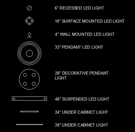
- [STEP 12] Add [A-CLNG-FIXT], color – 190, lineweight – 0.25mm > Place lighting symbols (blocks) in the floor plans > Switch the light symbols to [A-CLNG-FIXT]
- [STEP 13] Select all lighting symbols from the floor plans > Create a block [000-lighting fixtures] > Move the block to the RCPs
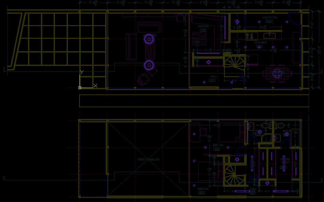
- [STEP 14] Select the block on the RCPs> Mouse right-click > Select [Edit Block in-place] > Adjust and align the lighting fixture with add dimensions > Click [Save changes]
(CO 2) Add /Edit Hatch
- [STEP 1] Hide unnecessary layers for better hatch results
- Confirm the current layer is [0] layer
- Turn off all layers except [0], [A-WALL], [A-LWT-SECTION], and [A-CLNG] layers
- [STEP 2] Draw lines or pline to create a closed object
- Hatch only recognizes a closed object. Thus you must make a closed pline or lines that are completely closed. If you are unsure the object is closed or not, you have to try the Hatch command first. If the hatch command doesn’t work, you have to redraw using [PLINE] or use [PEDIT] to convert from lines to [pline].
- Hatch only recognizes a closed object. Thus you must make a closed pline or lines that are completely closed. If you are unsure the object is closed or not, you have to try the Hatch command first. If the hatch command doesn’t work, you have to redraw using [PLINE] or use [PEDIT] to convert from lines to [pline].
- [STEP 3] Add hatch for the wall
- Confirm the current layer is [A-WALL]
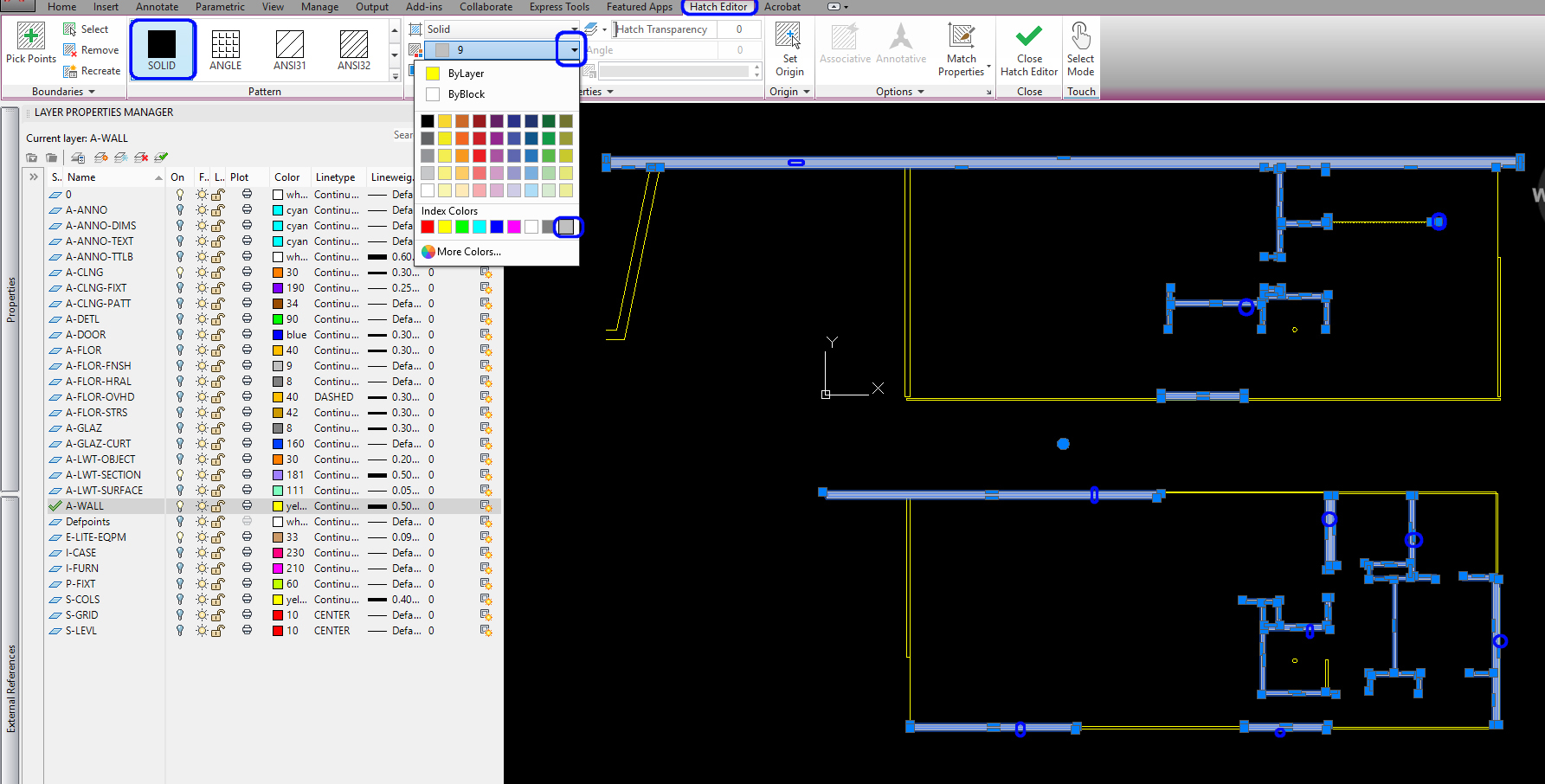
- Click the Hatch icon from the [HOME] tab, on the Draw panel
or, type [H] and press [ENTER] - Select Solid from the [HATCH EDITOR] tab, on the [PATTERN] panel
- Select color nine from the [HATCH EDITOR] tab, on the [PROPERTIES] panel
- As you move your mouse cursor over a closed object, the hatch pattern fills the area. If you don’t get the preview, that means you don’t have a closed object.
- You can select multiple files for one hatch command
- Press [ENTER] to finish the hatch command
- [STEP 4] Copy wall fills to RCPs
- Select the wall fills you just made. if necessary, you also can make a block for the wall fills by typing [B] and press [ENTER]
- Change drawing order to [SEND TO BACK] by clicking mouse right-click and select [SEND TO BACK]
- Copy the wall fills from the floor plans to the RCPs
- [STEP 5] Add hatch for the section view
- Select the section view
- Mouse right-click > select [EDIT BLOCK IN-PLACE] > Click [OK]
- Draw lines or polylines to make a closed object. Make sure you are in a correct layer
- Select [HATCH] icon from [HOME] tab, on [DRAW] panel
or, Type [H], and press [ENTER] key - Select a closed wall, floor, ceiling area. You can select multiple areas for one hatch—Press the [ENTER] key to finish the comment.
- Update the hatch fill layer to [A-LWT-SECTION]
- Once you finish hatching, click [SAVE CHANGES] to save the block > Click [OK]
- [STEP 6] Turn on all layers
The Hatch command is to fill an enclosed area or a selected-closed object with hatch patterns or fill.
Hatch is often used to add a fill to the wall, floor, and ceiling thickness for better readability.
Moreover, the hatch is also used to add patterns on a surface to express the finishes.
In this tutorial, you will practice adding solid fills on the wall of the floor plans and RCPs. This is commonly referred to as poche. Additionally, add a hatch pattern on the wall, floor, and ceiling of the section view.
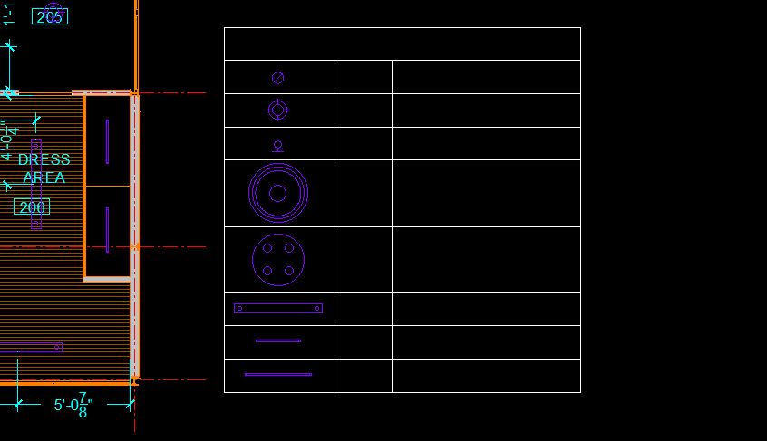
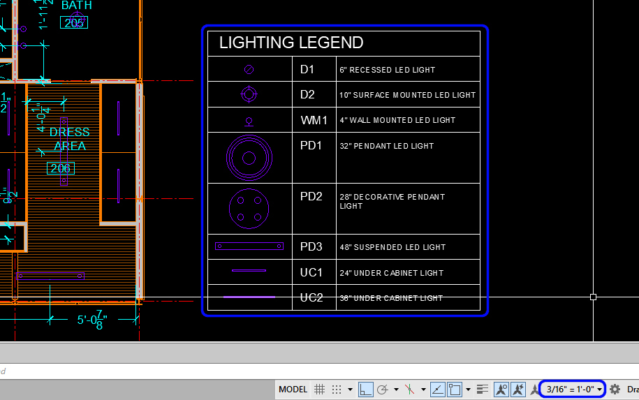
(CO 3) Create a legend for the RCPs
In your RCPs, a legend is necessary to inform what items are included, such as lighting fixtures, finishes, equipment, HVAC, and more that are used in your RCPs.
In this tutorial, you will make a lighting legend that you used in your RCPs
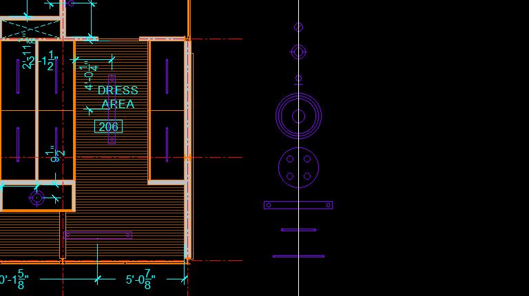
- [STEP 1] Find/organize the lighting fixtures that you used
- Copy the lighting block from the RCP to an empty drawing area
- Explode the lighting block by typing [X] and press the [ENTER] key
- Remove all dimensions from the exploded lighting block. You can lock the [A-CLNG-FIXT] > select the dimensions > delete the selected dimensions by press the [DELETE] key, or type [ERASE] and press the [ENTER] key
- Delete duplicated lighting fixtures. You only need one lighting fixture block of each lighting fixture type.
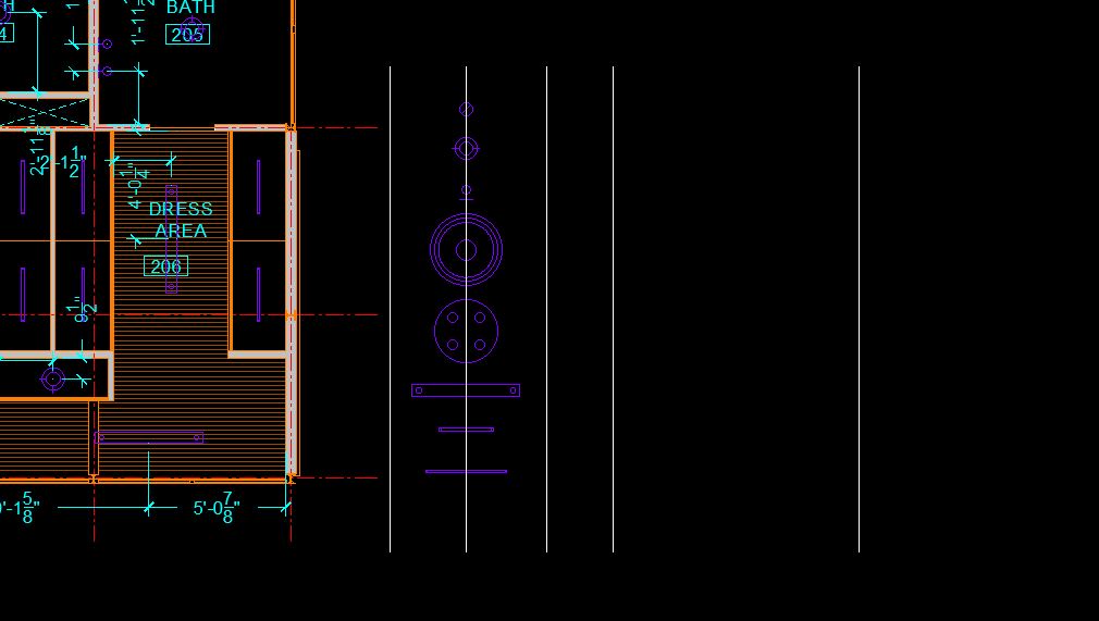
- Organize the lighting fixtures vertically. You can draw a line for a reference.
- [STEP 2] Create a table with lines
- AutoCAD offers a Table tool to create a table. You can find the tool from the [ANNOTATE] tab under the [TABLES] panel. However, this table tool is used for very complicated documents. As an interior designer with more than ten years’ experience in the industry, I still use lines to create a table. Please try the table tool if you want.
- Copy the reference line for the column lines for the table. You can use the [OFFSET] command, too.
-
- Draw rows with lines
- To clean up lines, use [TRIM] commands
- [STEP 3] Add texts to the table
- Make sure your drawing scale is 3/16”=1’-0.”
- Type [MT] and press [ENTER] to draw a text box and add text
- Repeat the [MTEXT] command for other text. You also can copy from what you created.
- [STEP 4] Select the table and table contents > Switch to [A-ANNO] layer
- [STEP 5] Make the table as a block [000-Lighting Legend]
SAVE the file before closing the application.
Save in a different location for the backup (e.g., a cloud folder)
