
Part Two. Revit
Chapter 10. Set grids, levels, dimensions, & building columns
Upon completing this session, students will be able to:
- (CO 1) Import CAD drawings- Floor plans, building elevations, and sections
- (CO 2) Adjust and verify the scale
- (CO 3) Create and modify grids and levels
- (CO 4) Create plan views- Floors and ceilings
- (CO 5) Create columns
 Session Highlights
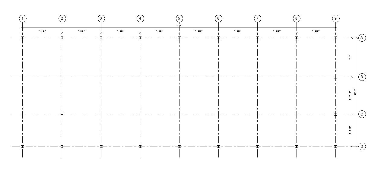
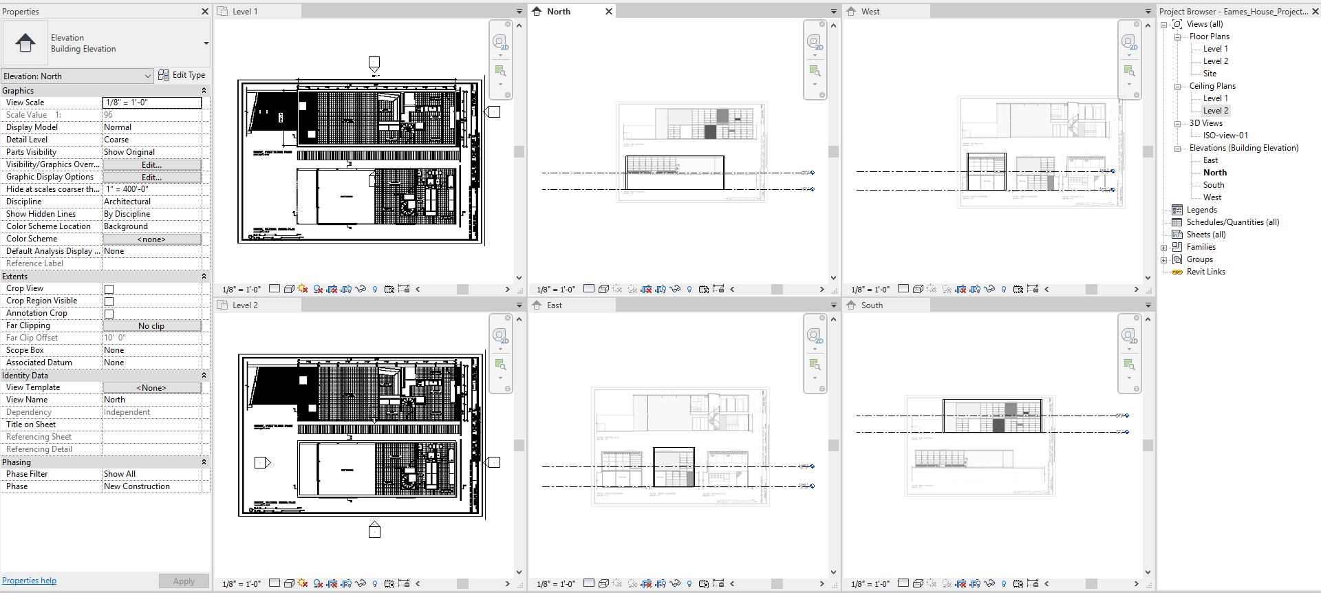
At the end of the session, students can create the graphics below.
 Lecture Contents
(CO 1) Import Drawings- Floor plans, building elevations, and sections
Prepare Drawings before import CAD drawings
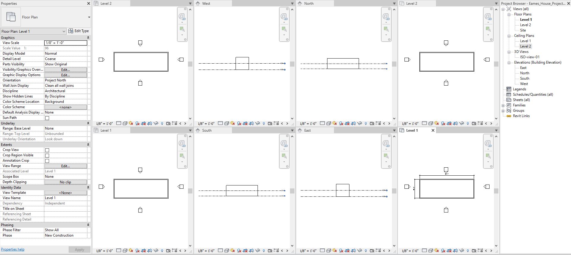
- [STEP 1] Open Revit application > Open your project > Double-click [LEVEL 1] from [PROECT BROWSER] > Close all other views except [LEVEL 1]
- [STEP 2] Select [SITE] information including the property line, trees, and neighborhood buildings > Mouse right-click on one of the selected elements > select [HIDE IN VIEW] > Select [ELEMENTS] or [CATEGORY]
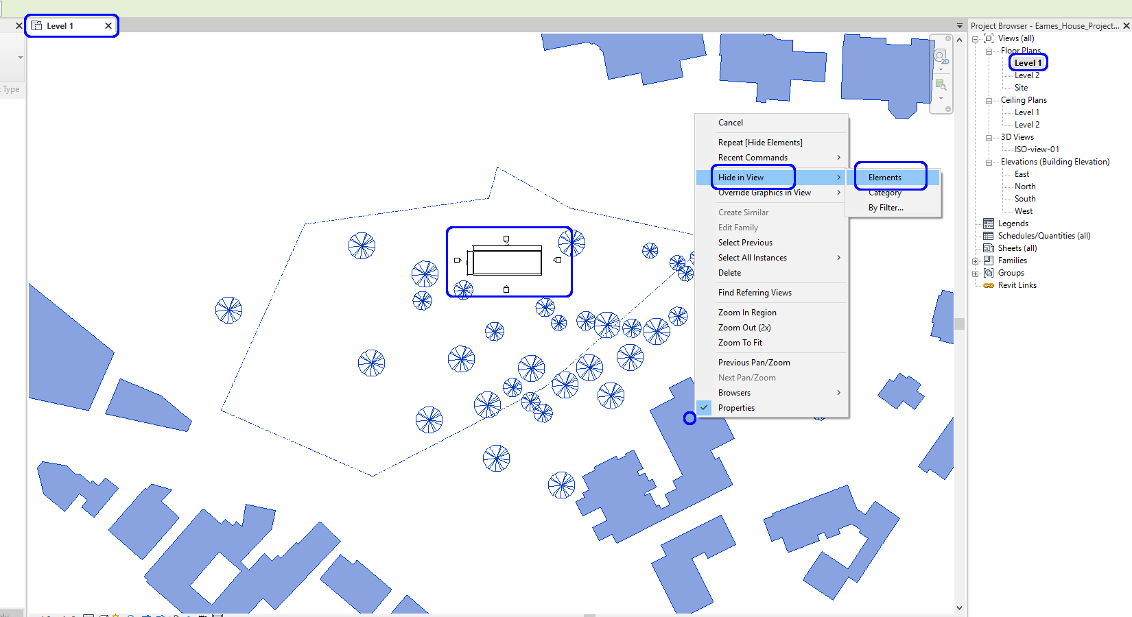
Repeat this process for FLOOR PLAN – LEVEL 2, ELEVATION – EAST, WEST, NORTH, SOUTH, CEILING PLAN – LEVEL 1, LEVEL 2
Insert drawings
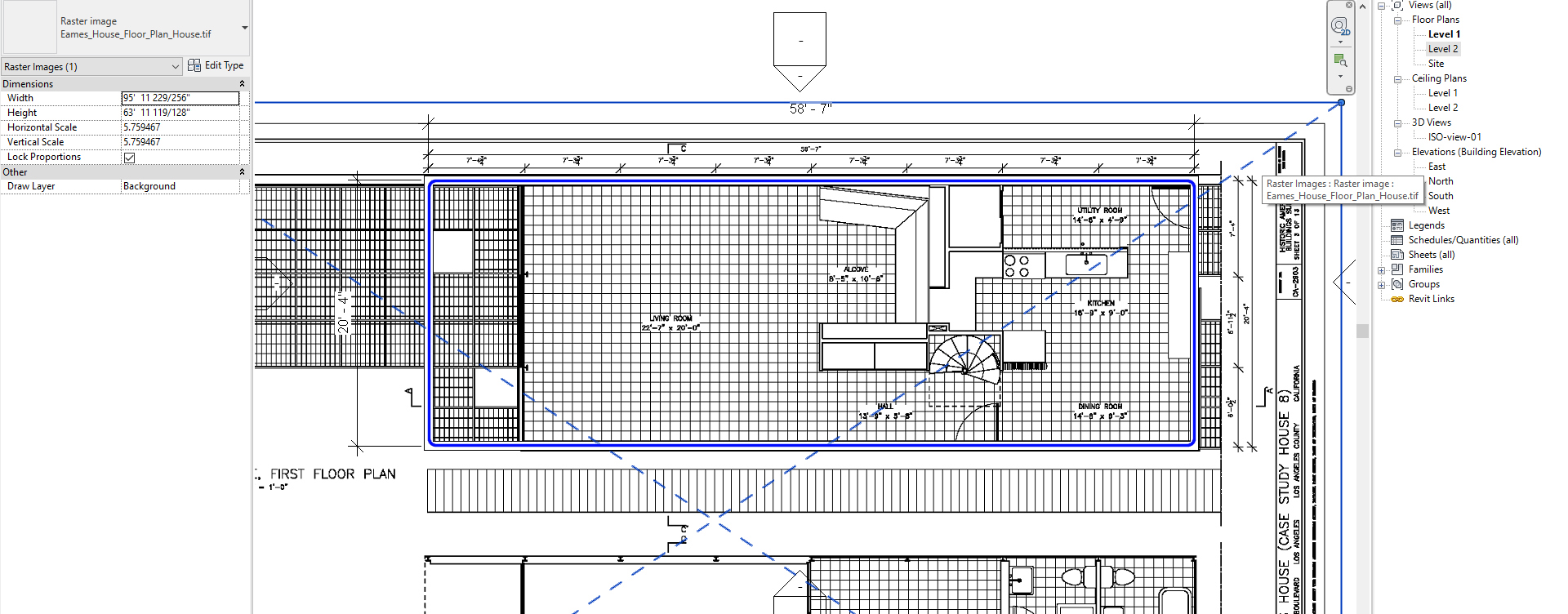
In this tutorial, we will practice how to add an image (drawing) to the view. You can insert CAD files and PDF files
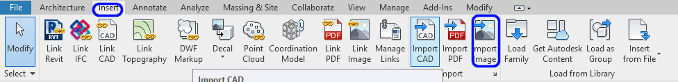
- [STEP 1] Select [IMPORT IMAGE] from [INSERT] tab, under [IMPORT] panel
Note. Revit can import various file types – dwg, dxf, pdf, jpg, tif, rvt, and more
Note. For this project, I will use [tif] files
- [STEP 2] Find the folder where the drawings are saved > select the floor plan > click [OPEN] > place the imported image on the view [LEVEL 1]
Repeat this process for FLOOR PLAN – LEVEL 2, ELEVATION – EAST, WEST, NORTH, SOUTHNote. The imported image will only show on the view where you placed.
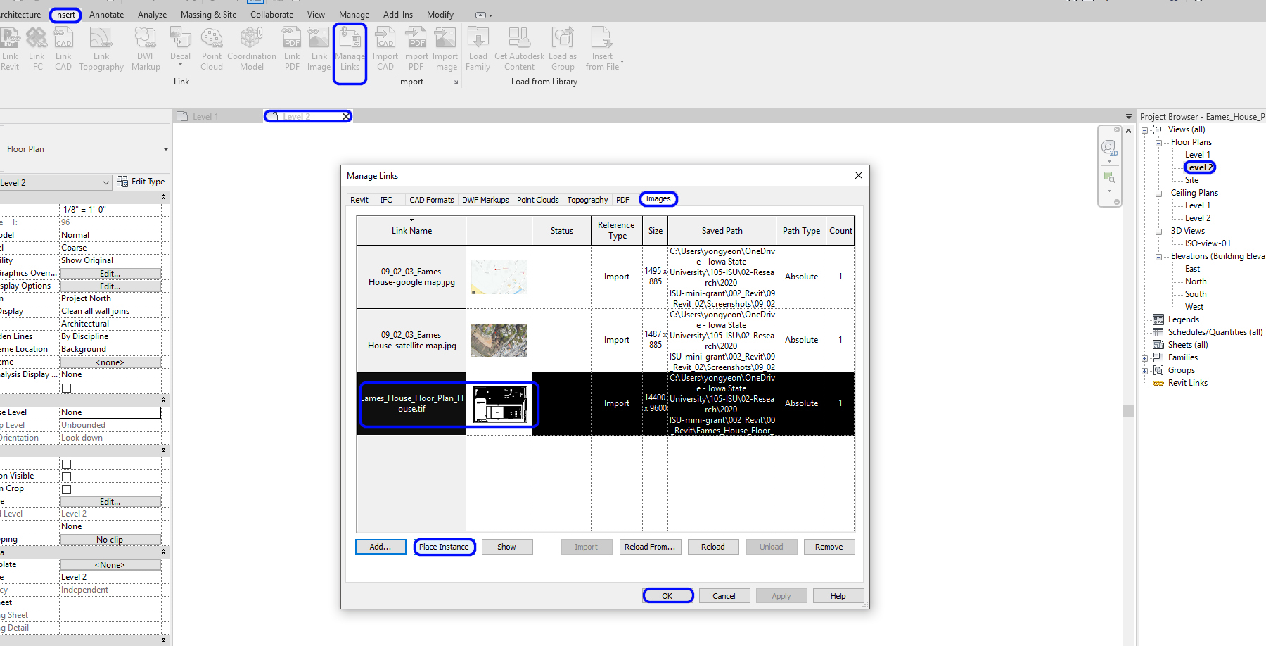
Note. To use the image file that you imported for your other level like [LEVEL 2]. Click [MANAGE LINKS] > Click [IMAGES] tab > Click the image that you loaded in the model > Click [PLACE INSTANCE]
(CO 2) Adjust and verify the scale
Confirm the scale and position of the imported drawings
If the imported image/CAD file/PDF is in the right scale and position, skip this one, but double-check for your accuracy
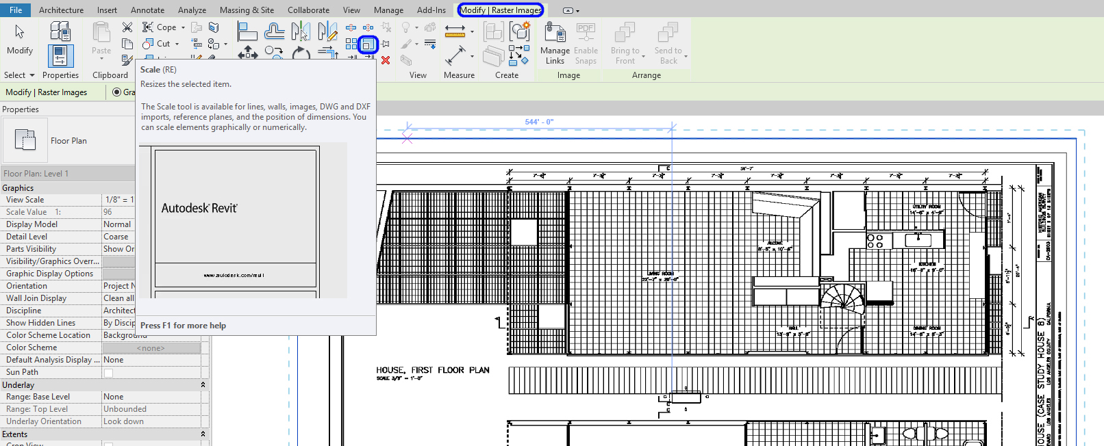
- [STEP 1] Select imported image > click [SCALE] from [MODIFY] tab, under [MODIFY] panel
- [STEP 2] Click the first point that you know the dimension. I will use the overall building dimension (58’-7”). You may also use a graphic scale if you have one
You need to zoom in to select the first point in the middle of the dimension line.
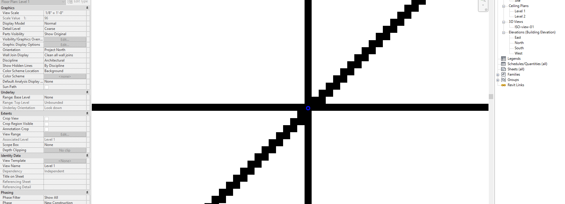
- [STEP 3] Click the second point
- [STEP 4] Type the dimension [58’7”] and press [Enter] key
- [STEP 5] Zoom out to see the position
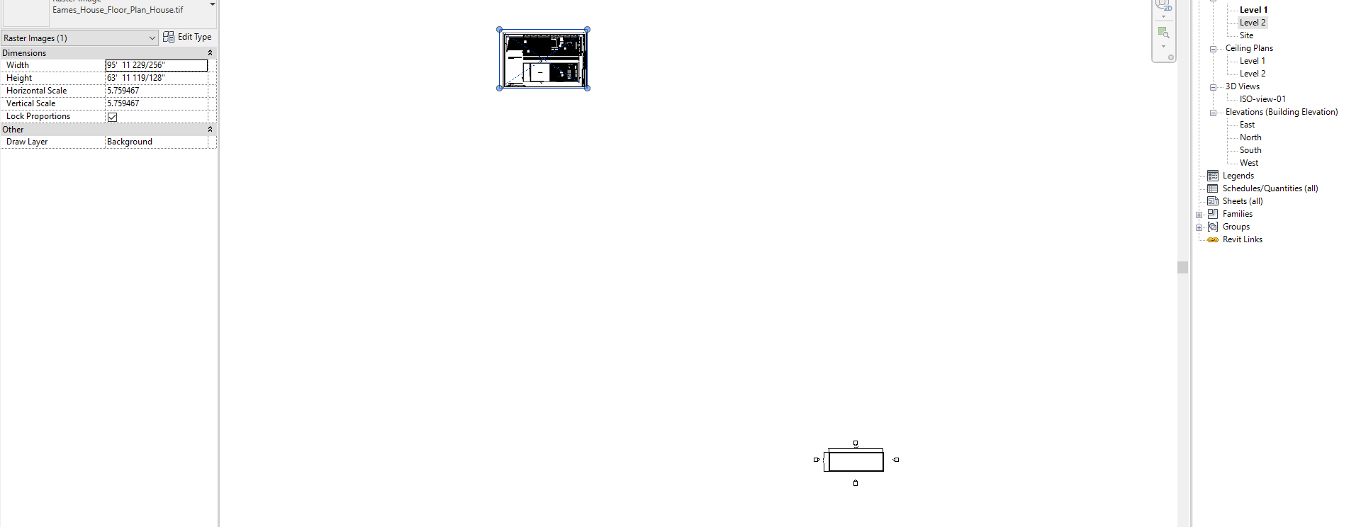
- [STEP 6] Move the drawing to match the base drawing. You can use a specific point to match the drawing to the base Revit model that you created
You may need to change the graphic display to [WIREFRAME] to see the image behind the model
Repeat this process for FLOOR PLAN – LEVEL 2, ELEVATION – EAST, WEST, NORTH, SOUTH
(CO 3) Create and modify grids and levels
Create grids
- [STEP 1] Open [LEVEL 1] view
- [STEP 2] Select [GRID] from [ARCHITECTURE] tab, under [DATUM] panel
- [STEP 3] Using the straight-line selection, hover over the view near the west wall until it becomes highlighted in the center of the wall and an “X” appears
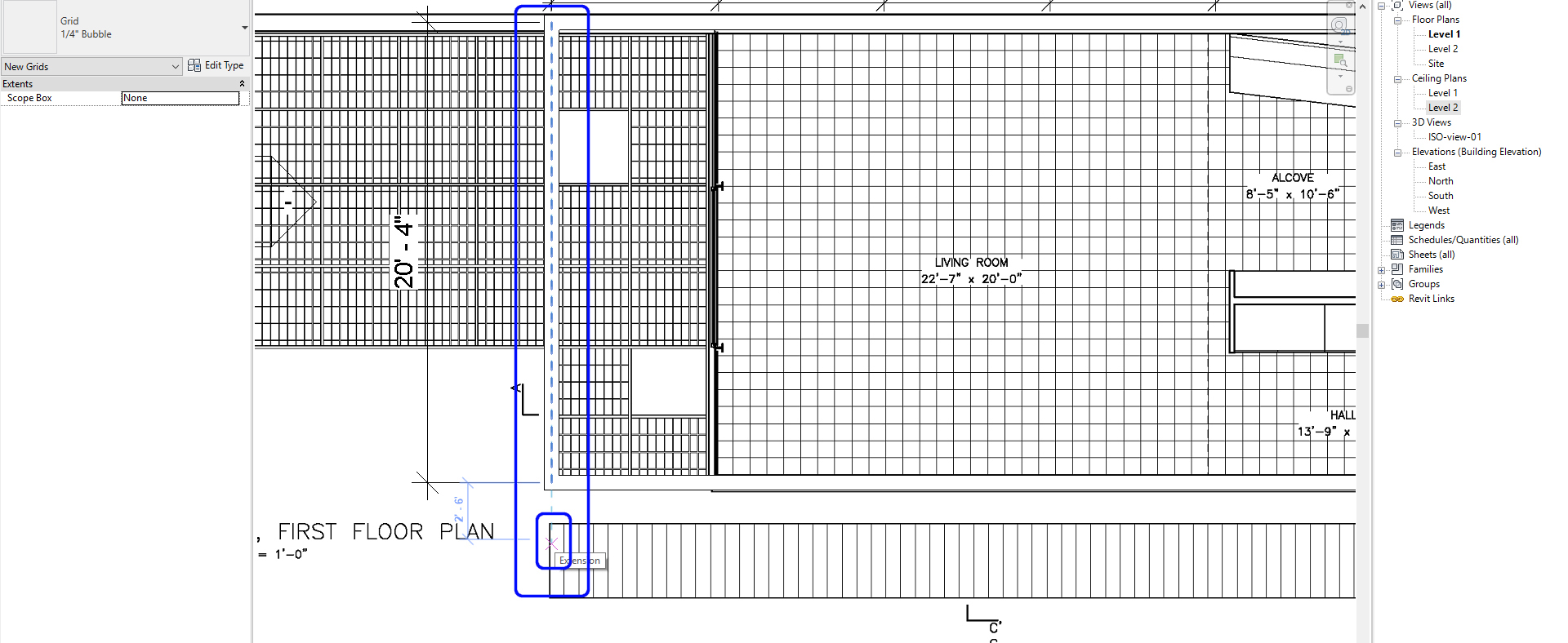
- [STEP 4] Click the first point and click the second point to complete the gridline 1
- [STEP 5] To complete the remaining gridlines, you can copy or continue drawing gridlines based on the imported image
- [STEP 6] To copy, select the Revit gridline 1 that you just made. Select the Copy tool and click a point and specify the second point to the next grid line
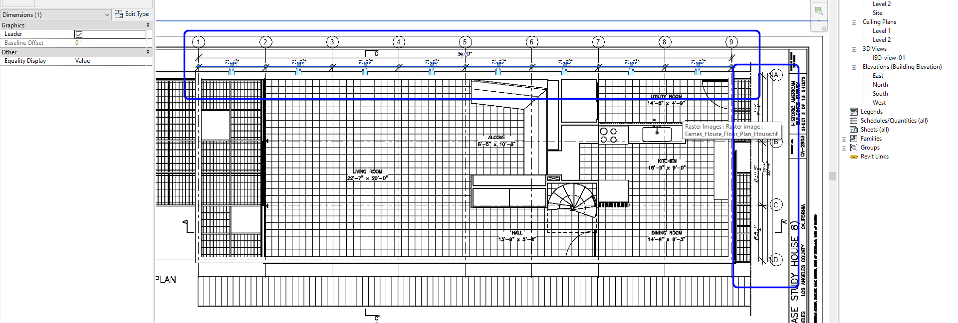
- [STEP 7] Also you should use dimension [DI] to specify the distance between gridlines
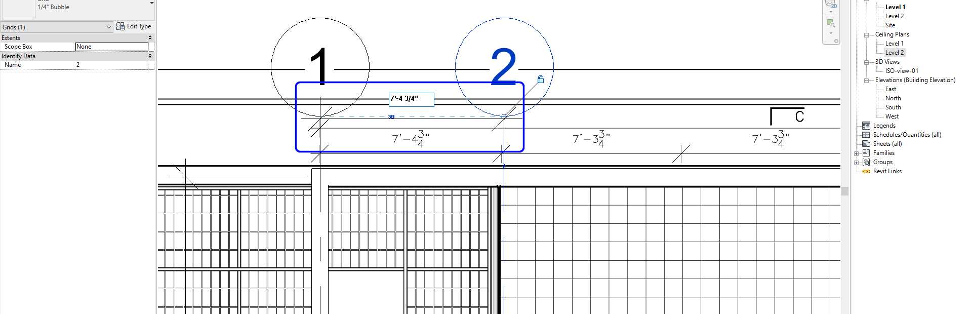
- [STEP 8] Continue to copy all North/South gridlines
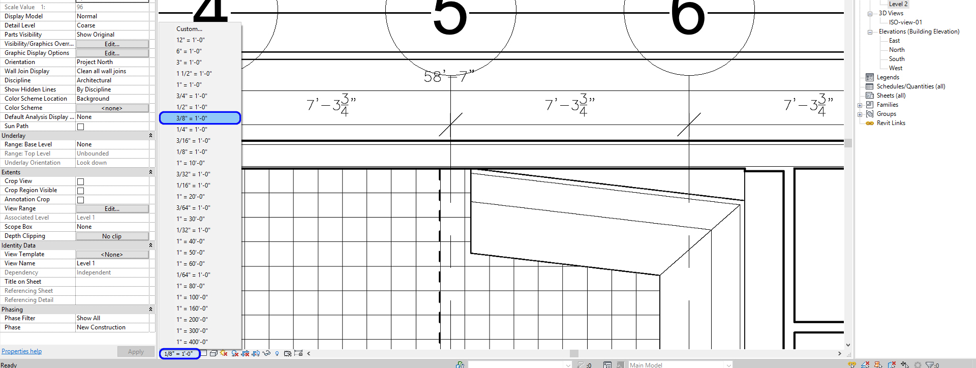
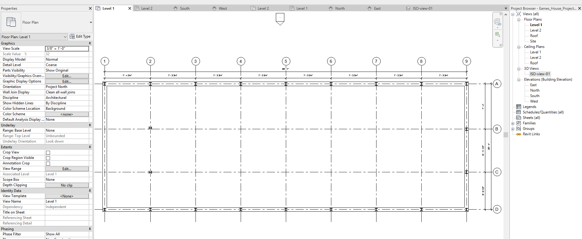
- [STEP 9] If the grid bubble and numbers are too big, you can update the view scale by clicking scale. For the Eames House project, use 3/8” = 1’-0”
- [STEP 10] Create a Horizontal new grid for East/West. And Update the Grid name to [A] and complete East/West grids
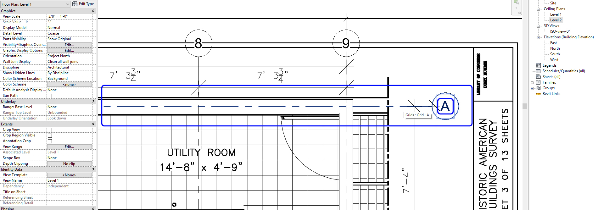
- [STEP 11] Your gridlines and dimensions can be locked
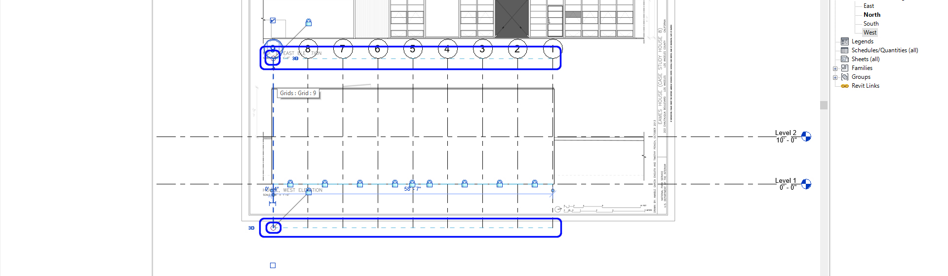
- [STEP 12] Open [NORTH] view and adjust the grid line heights by dragging and drop the edge of the grid line. And repeat this for [WEST] view
Create and Modify levels
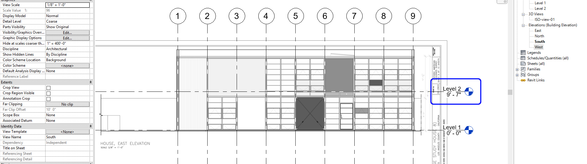
- [STEP 1] We will now make Levels. Begin by navigating to the [SOUTH] elevation in the Project Browser.
- Adjust the length of the level by dragging and drop the edge of the level line
- Repeat this for [EAST] elevation view
- [STEP 2] After you have confirmed that Levels 1 & 2 are set to the correct elevation, you can add additional levels. To adjust the elevation number, click on the number and type in the correct elevation.
Note: Level 2 will be [9’-7”] higher than Level 1.
- [STEP 3] Add a roof level.
- Select [LEVEL] from [ARCHITECTURE] tab, under [DATUM] panel
Or, type [LL] - Click the left corner of the level and click the second point to finish the command
- Rename [Roof] > Click OK in the window pop-up and change the view name accordingly
- Adjust the height to [18′ 5 1/2″]
- Select [LEVEL] from [ARCHITECTURE] tab, under [DATUM] panel
- [STEP 4] If you copy (CO)the level from the existing level, the view will not be created. Create Ground and Level 1 top (Black symbol)
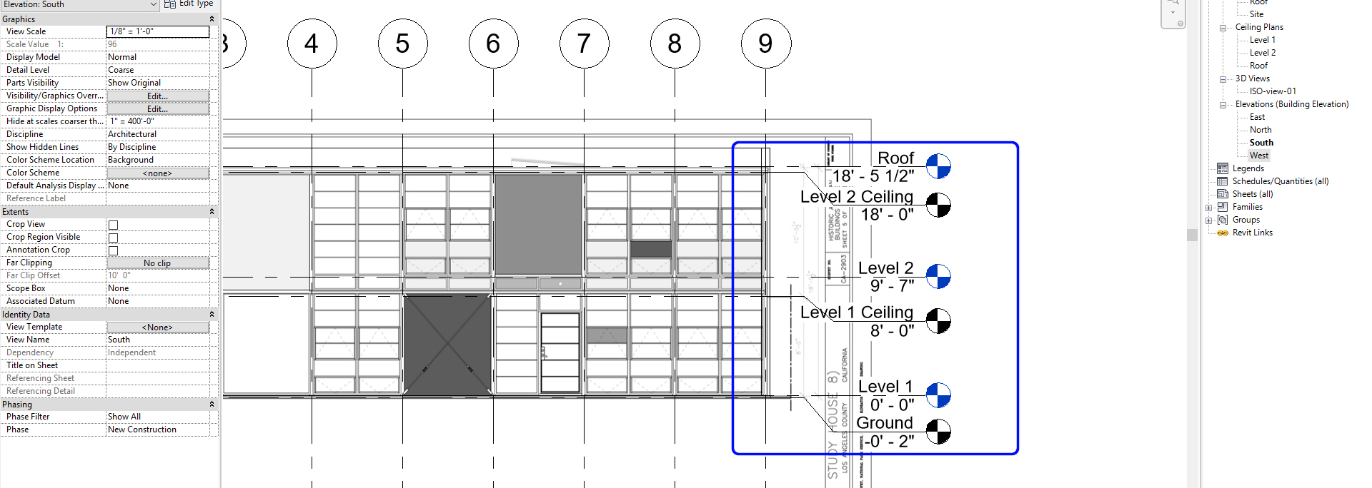
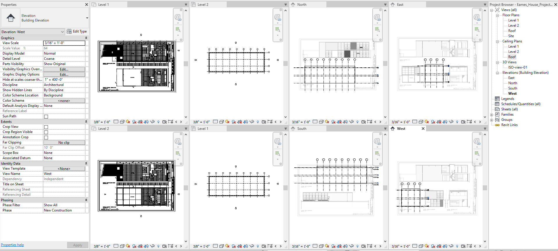
- [STEP 5] Update the view scales
- 3/16” = 1’-0” for all elevations
- 3/8” = 1’-0” for floor plans and ceiling plans
(CO 4) Create plan views- Floors and ceilings
Currently, you have what you need. When you add a new level [LL], the views automatically created. If you made the view by coping existing levels [CO], you have to create new views for the level
- [STEP 1] Select [PLAN VIEWS]
- [STEP 2] Select [FLOOR PLAN] if you need a floor plan
- [STEP 3] Select [NAME OF THE LEVEL] and click [OK], then you can find the view from [PROJECT BROWSER]
If you need additional plans for furniture plans, power, and data plans, and finish plans, you need to duplicate the view by mouse-right clicking and select duplicate view > duplicate
Note, there are three options for duplicating views. Please refer to this link for further explanation
(CO 5) Create columns
We will now add columns beginning on the Ground level
- [STEP 1] Under the Architecture tab on the Ribbon select Structural Column.
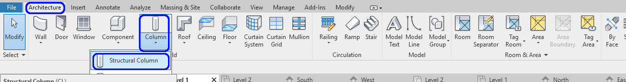
- [STEP 2] Select the 5” x 5” column.
Note: an existing column family may need to be edited to create this size by clicking [EDIT TYPE] > Click [DUPLICATE] > add name [W5x 5] > click [OK] > update width and height to 5”
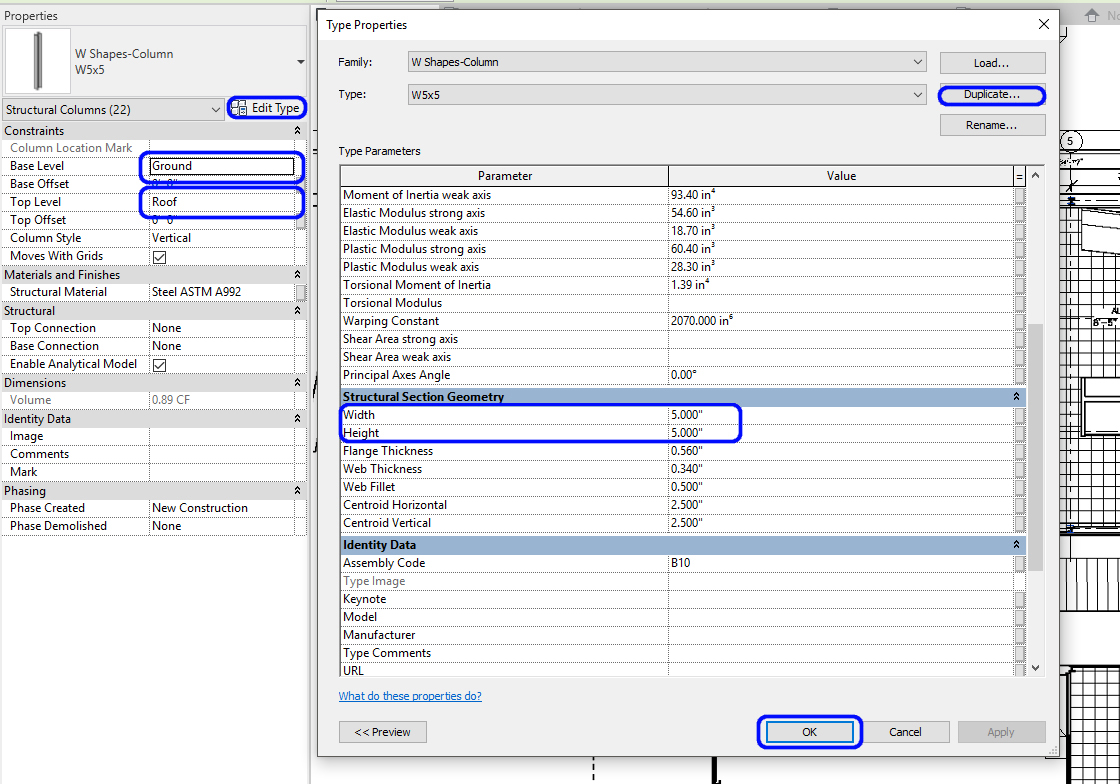
- [STEP 3] Confirm the Base Level is set to Ground and the Top Level is set to Roof
- [STEP 4] Place a column on your [LEVEL 1]
- [STEP 5] It will be necessary to Move [MV] and Copy [CO] the Revit columns to align as shown on the imported floor plan and the grid that you created
Hide the imported drawing image to confirm all columns are properly placed
Type [TL] to see the thick lines for print
SAVE the file before closing the application.
Save in a different location for the backup (e.g., a cloud folder)
 References
Autodesk.Help. (2007, September 13). About Duplicating Views in Revit. Retrieved October 22, 2020, from https://knowledge.autodesk.com/support/revit-products/learn-explore/caas/CloudHelp/cloudhelp/2018/ENU/3PP-RVT-ARCH-ASCENT/files/GUID-F4ABE31C-D4D8-45FB-A628-A512D41D8114-htm.html
