
Part Two. Revit
Chapter 17. Add/edit views, lighting, & materials
Upon completing this session, students will be able to:
- (CO 1) Set perspective views
- (CO 2) Set Isometric views
- (CO 3) Edit Views – Graphic Display styles
- (CO 4) Test Render
- (CO 5) Set sun
- (CO 6) Edit Artificial lighting
- (CO 7) Add/Edit materials
- (CO 8) Render material managements
 Session Highlights
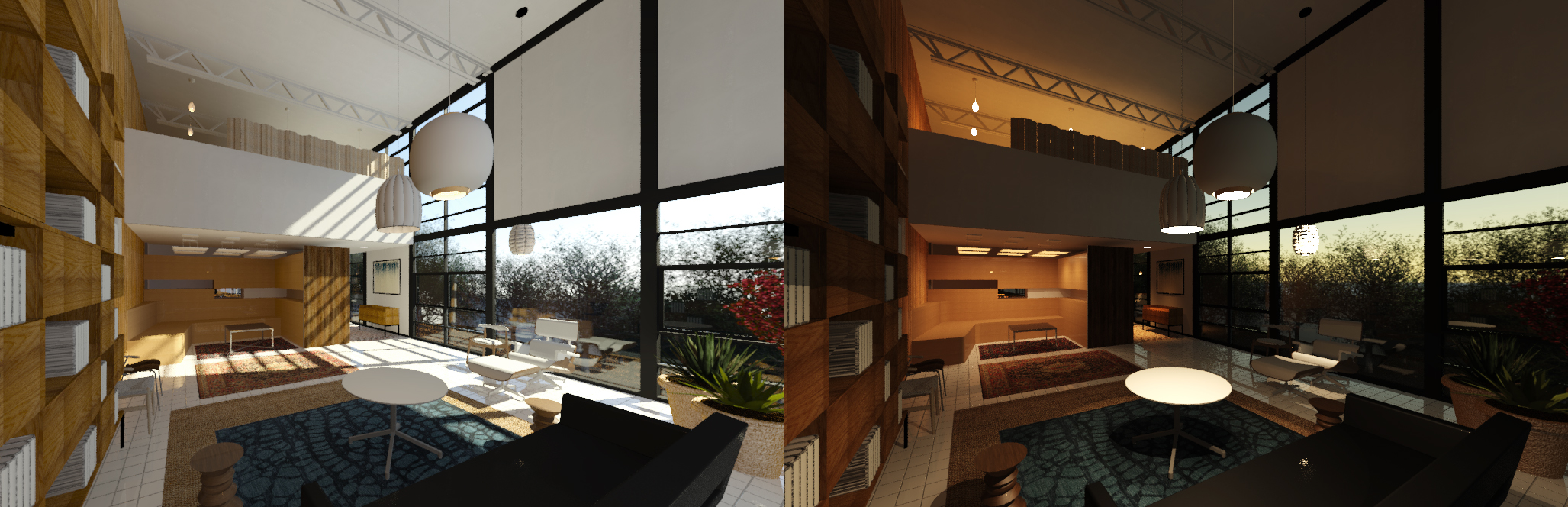
At the end of the session, students can create the graphics below.
 Lecture Contents
(CO 1) Set perspective views
Revit supports perspective views and isometric views.
For more information about 3D views, please read this page
To create a camera view for a perspective view
- [STEP 1] Open a floor plan [Level 1] to create a camera view
- [STEP 2] Click a drop down menu of [3D view] > [Camera view] from the [View] tab, under [Create] panel
- [STEP 3] On the floor plan, click the location of the camera position, click the target position > The perspective view will pop up the window.
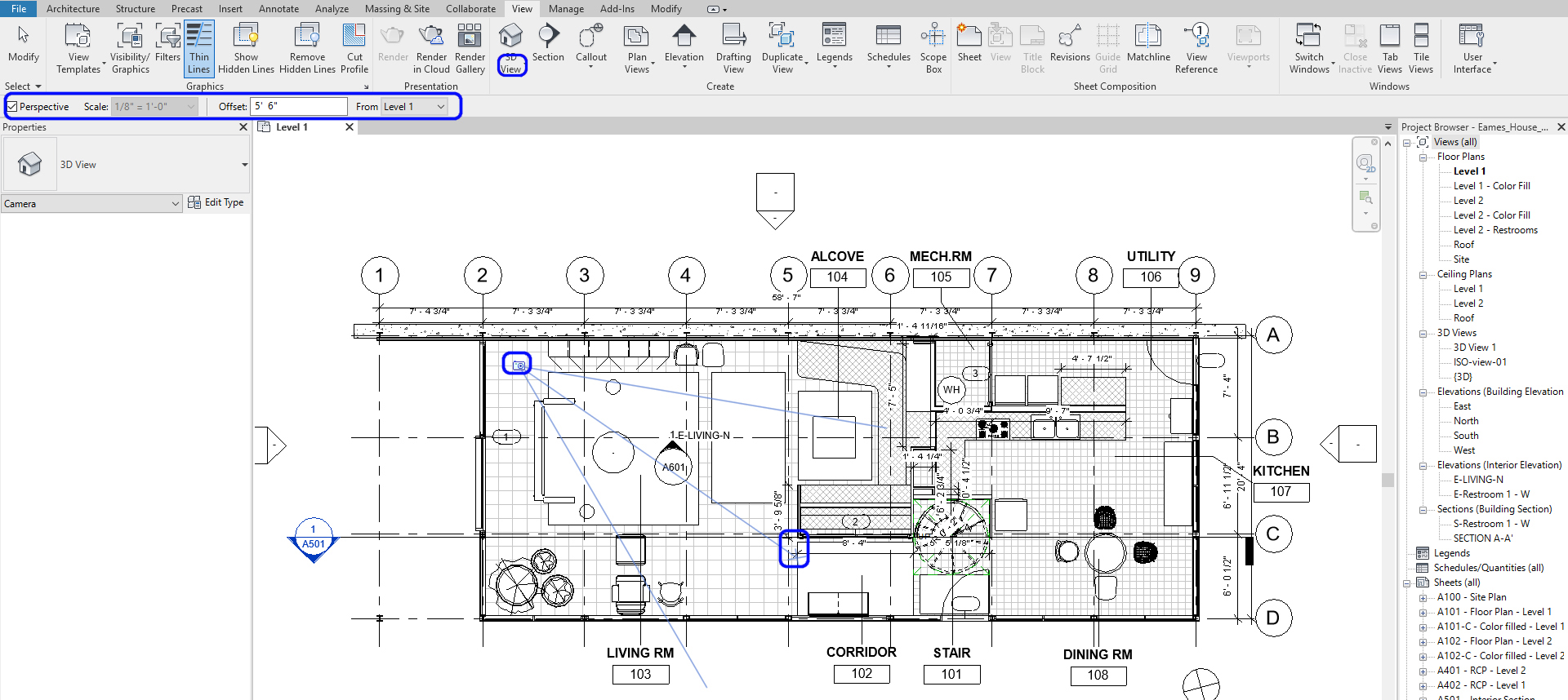
To reposition the camera view
- [STEP 1] In order to adjust the view, you will open the camera view that you would like to adjust and the floor plan together. Type (WT) to see the tile view and type (ZA) to see zoom in all
- [STEP 2] Click the frame of the perspective view > you can reposition by controlling the 3D wheel on the top-right corner of the view and resize the camera view by adjusting the nodes
- [STEP 3] You can also change the camera position and the target position on your floor plan. On the Properties panel, change eye elevation & Target elevation, turn off Far Clip Active, and view the name.
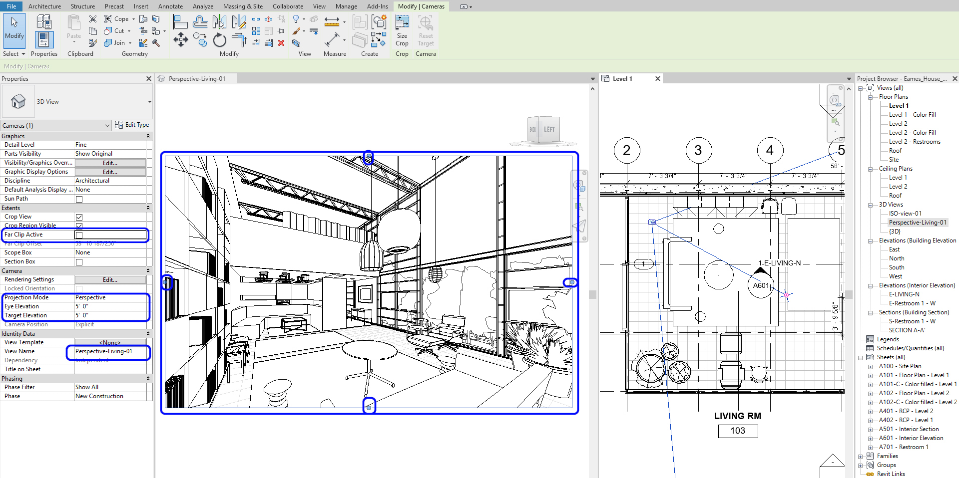
Image-print size update for the perspective view
- [STEP 1] Click the view frame
- [STEP 2] Click the [Size Crop] icon from the [Modify] tab
- [STEP 3] On Crop Region Size window, check [Scale (locked proportions)]
- [STEP 4] Change the width of what you want to make, and then the height will automatically change with the view ratio you made.
- [STEP 5] If you want to change the proportion, you check the [Field of view] and change the proportion. Click Apply.
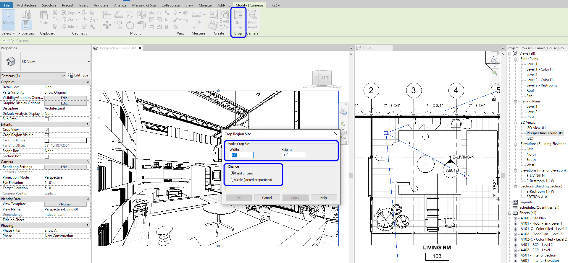
- [STEP 6] Then again, check [Scale] to change the size of the view
- [STEP 7] Click [ok] to finish
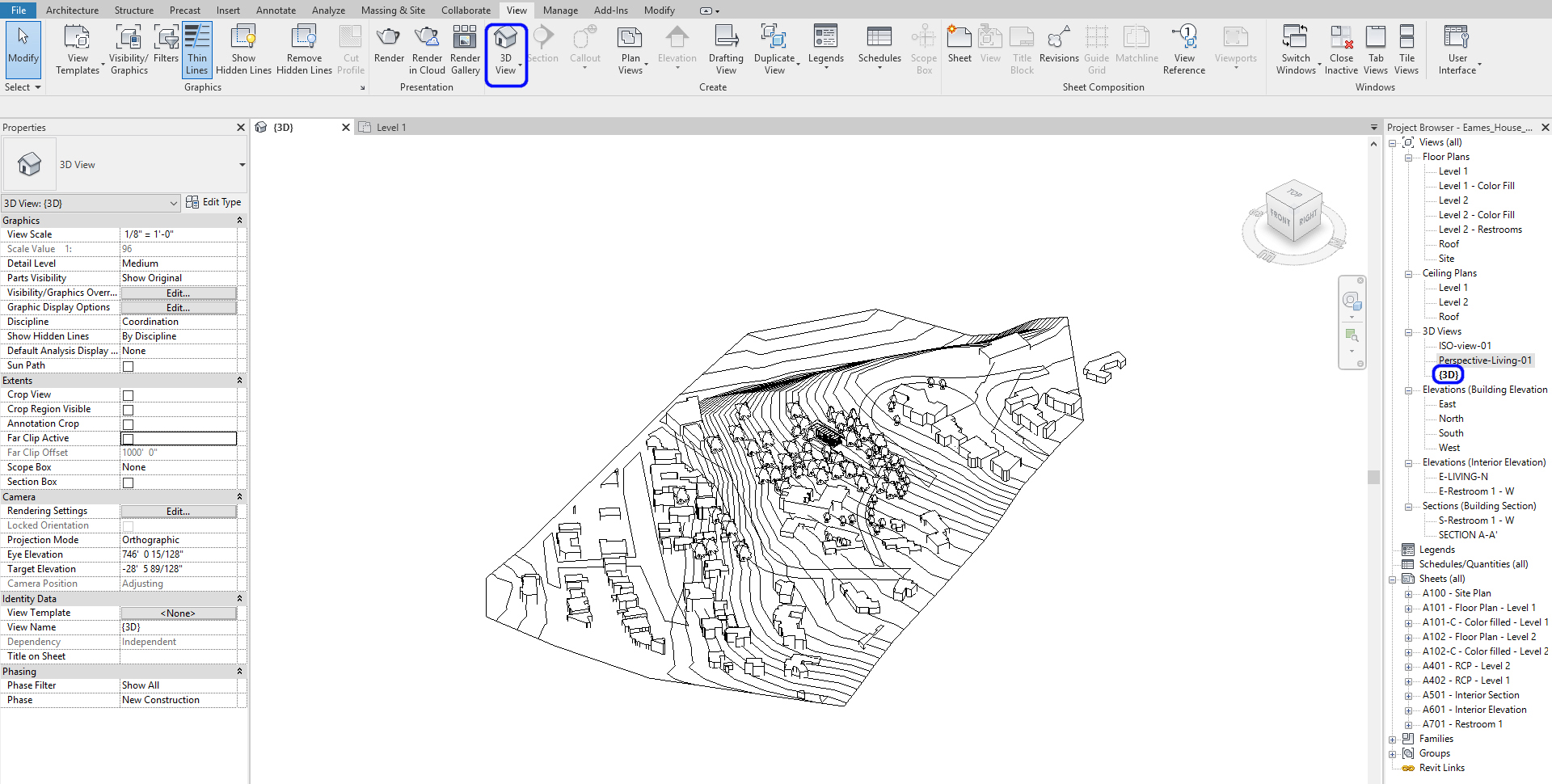
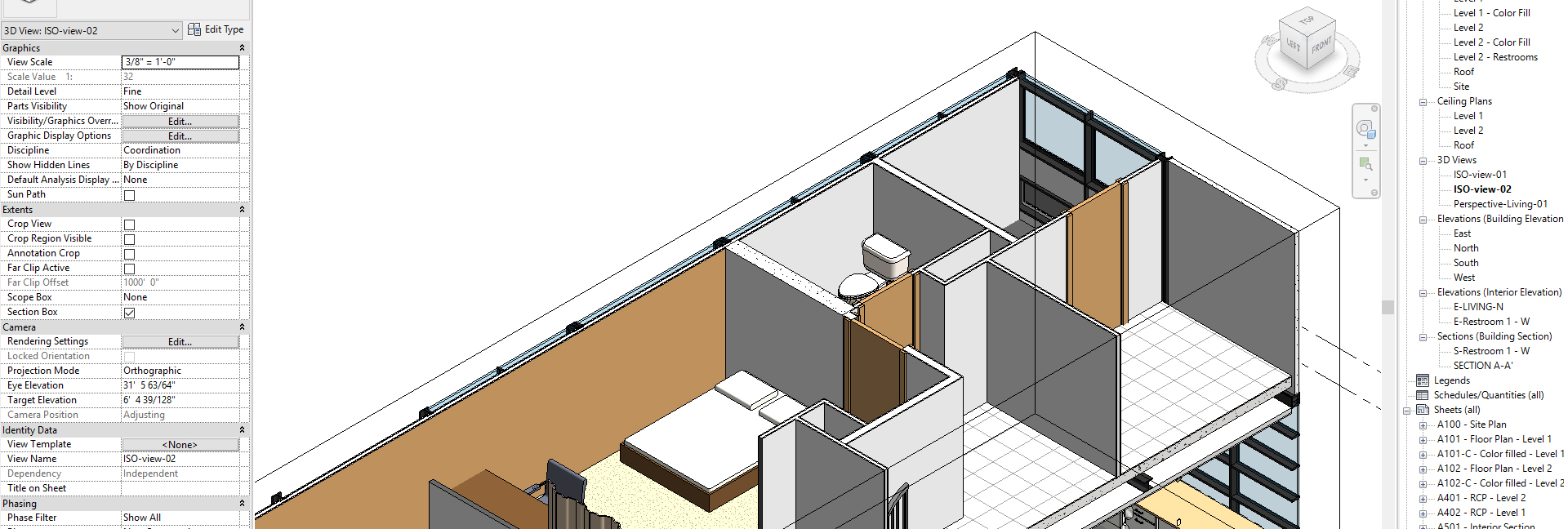
(CO 2) Set Isometric views
Set Isometric view
- [STEP 1] To add an Isometric view, Click the drop-down menu of [3D view] from the [view] tab, under [Create] panel, click [Default 3D view] > The Isometric view will pop up
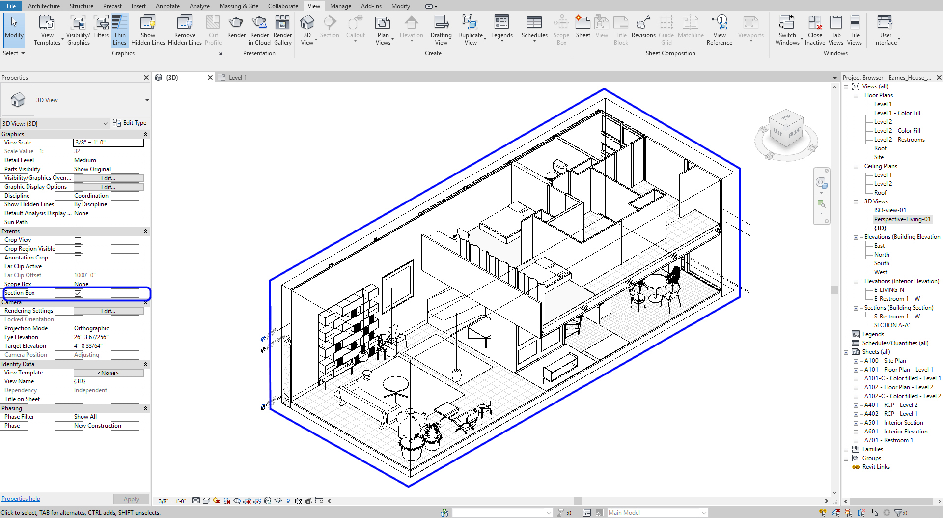
- [STEP 2] To edit the boundary of the view, Click the [section box] option on the [properties] palette
- [STEP 3] Click the [section box] on the view > Drag the arrows toward the model to create a dynamic slice of the model
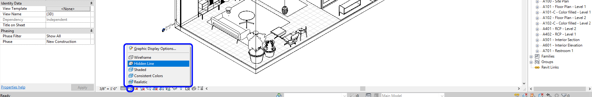
(CO 3) Edit Views – Graphic Display styles
To set the graphic display styles
- Once you click [Graphic Display] on the [view navigation] panel, click one of the six options, then you can change the styles of graphic
- Examples of the six graphic style preset
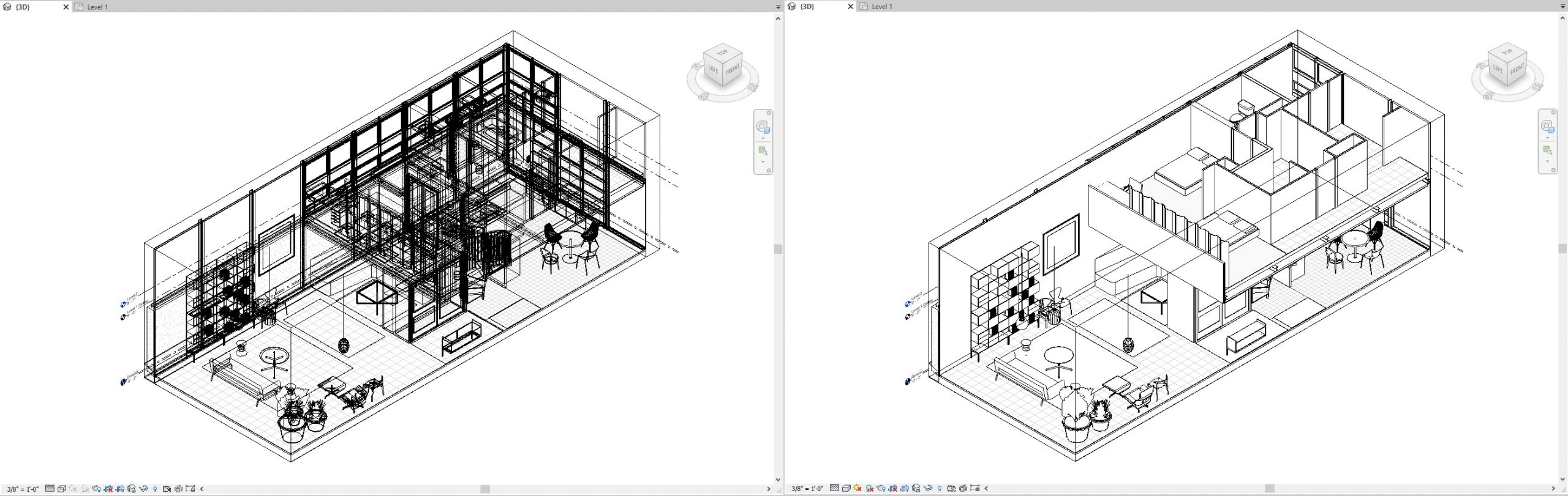
Wireframe & Hidden Line
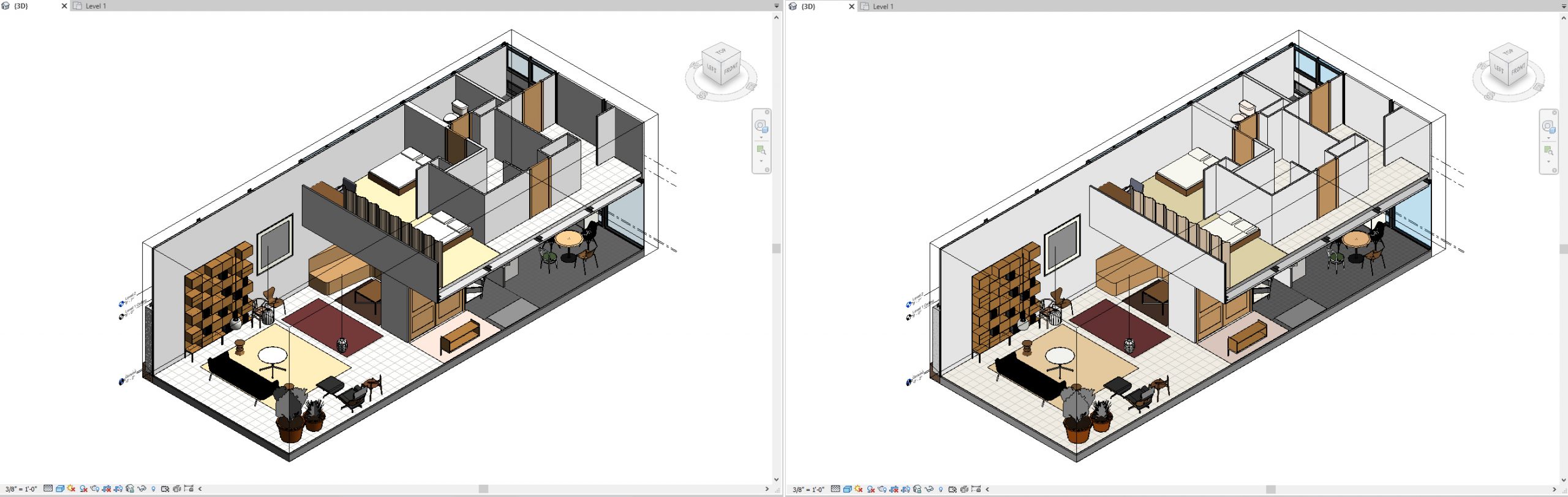
Shaded & Consistent Colors
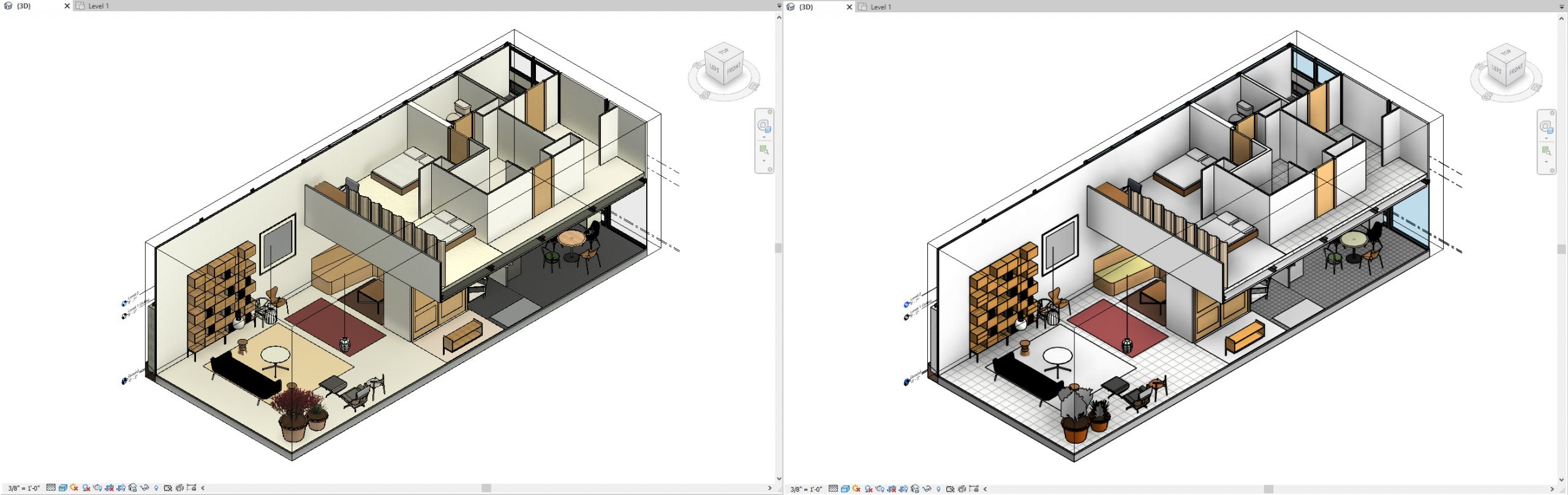
Realistic & Custom
To modify Graphic Display Options
- [STEP 1] Click [Graphic Display] on the [view navigation] panel > click [Graphic Display Options]
- [STEP 2] Modify the properties that are appropriate for your project
For a quick presentation, I like to use these settings
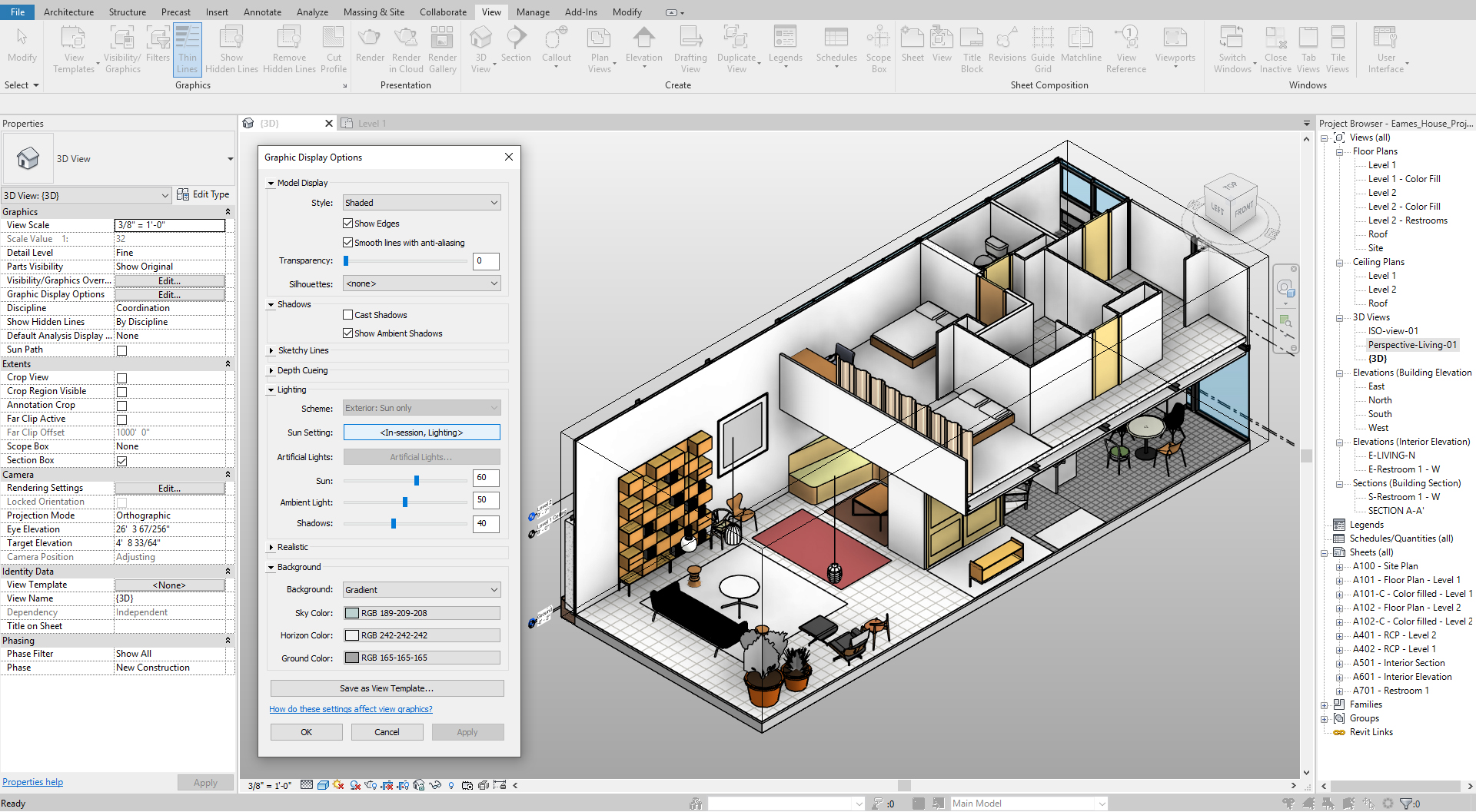
- [STEP 3] Click [Apply] to confirm what you changed, click [Ok] to set the style
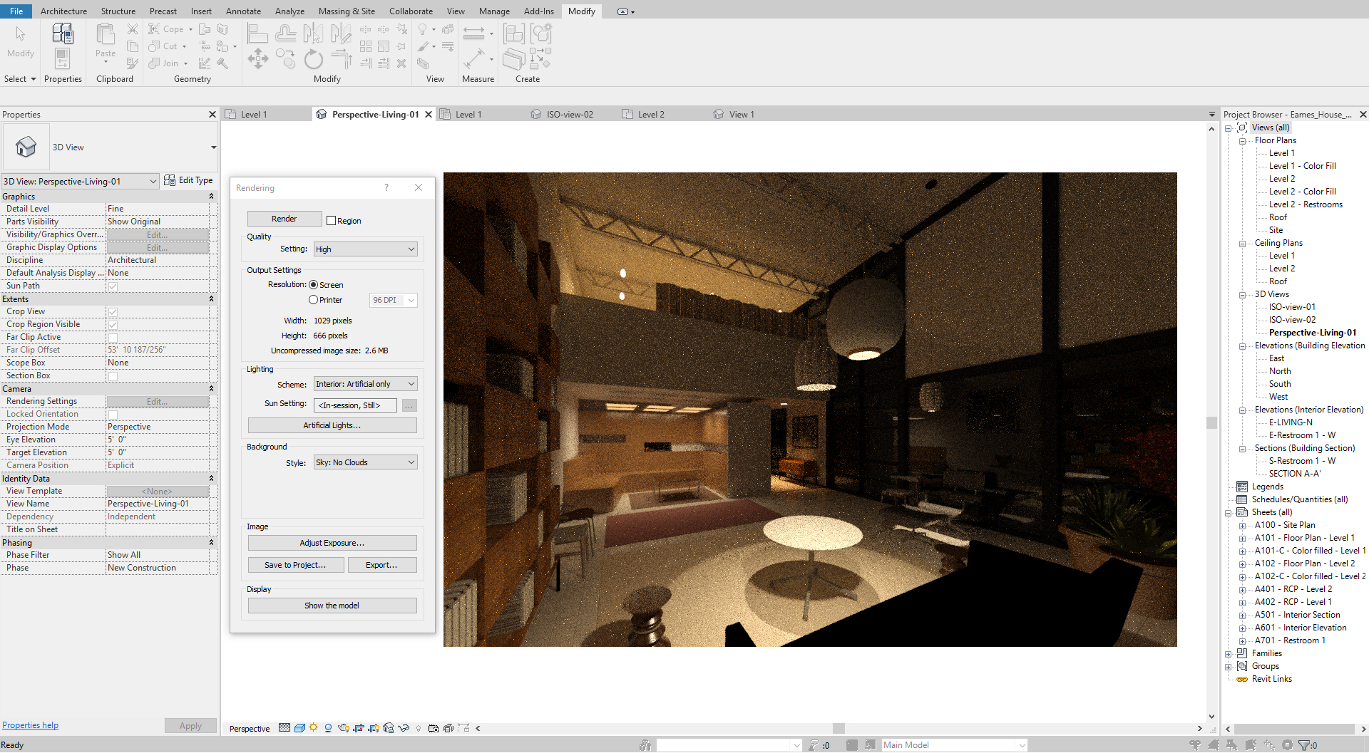
(CO 4) Test Render
To do a test render, you need to adjust the render settings
- [STEP 1] Click [Render] from the [View] tab, under [Presentation]
or Click [Rendering Dialog] on the [view navigation] panel - [STEP 2] Adjust settings
- Confirm Setting – Draft for a test render
- Change Lighting scheme – interior for an interior scene
- Change Sun Setting – Sun and Artificial
- Change Background style
- Click [adjust Exposure] if needed
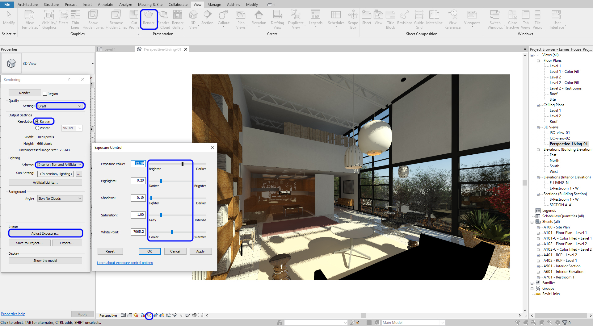
- [STEP 3] Click Render to see the result. You can stop if it shows all right, you do not need to wait until the completion.
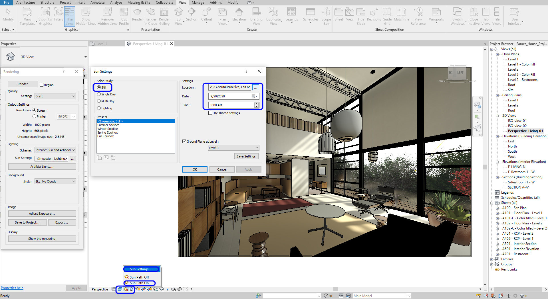
(CO 5) Set sun
Setting Sun
- [STEP 1] Click [Sun Path] On > Click [Shadow] On
- [STEP 2] Click Sun Settings to adjust sun direction
- [STEP 3] Select Still for a specific time
- [STEP 4] Change Display setting to Realistic or Render to see the sun direction and material
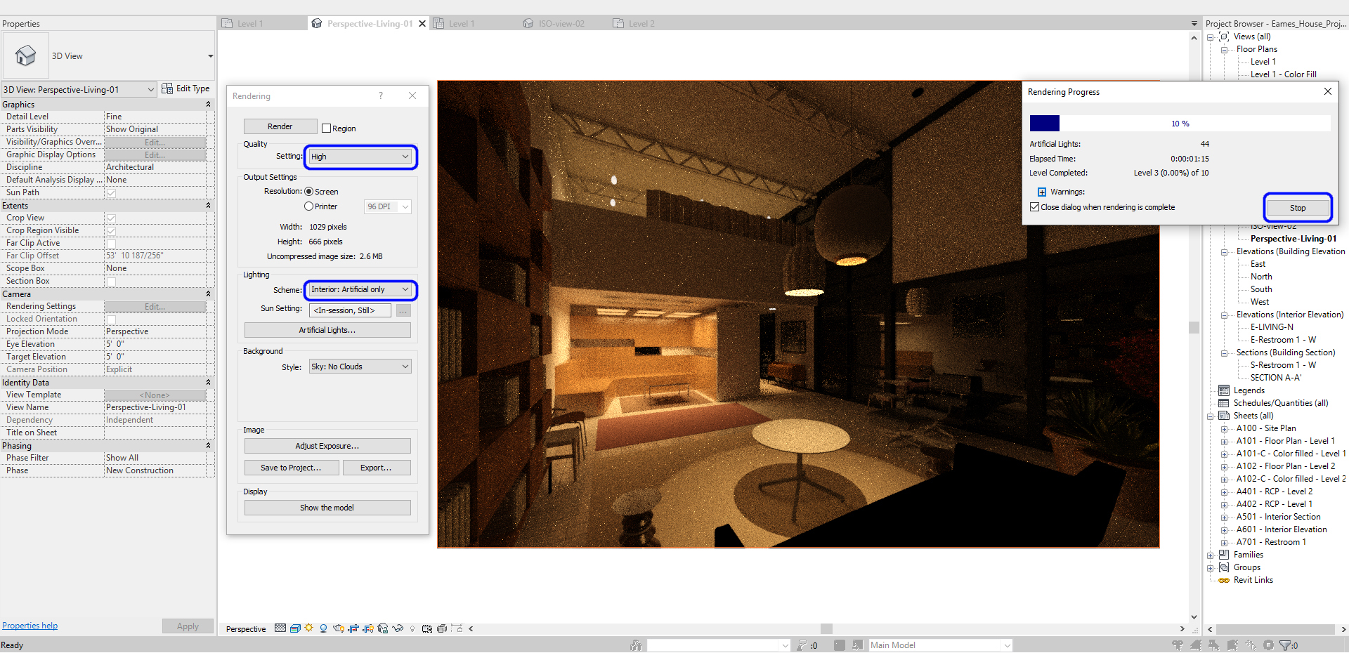
(CO 6) Edit Artificial lighting
Review the default lighting setting
- [STEP 1] To see an accurate lighting setting, change the render setting to [Interior: Artificial only] and [High] quality
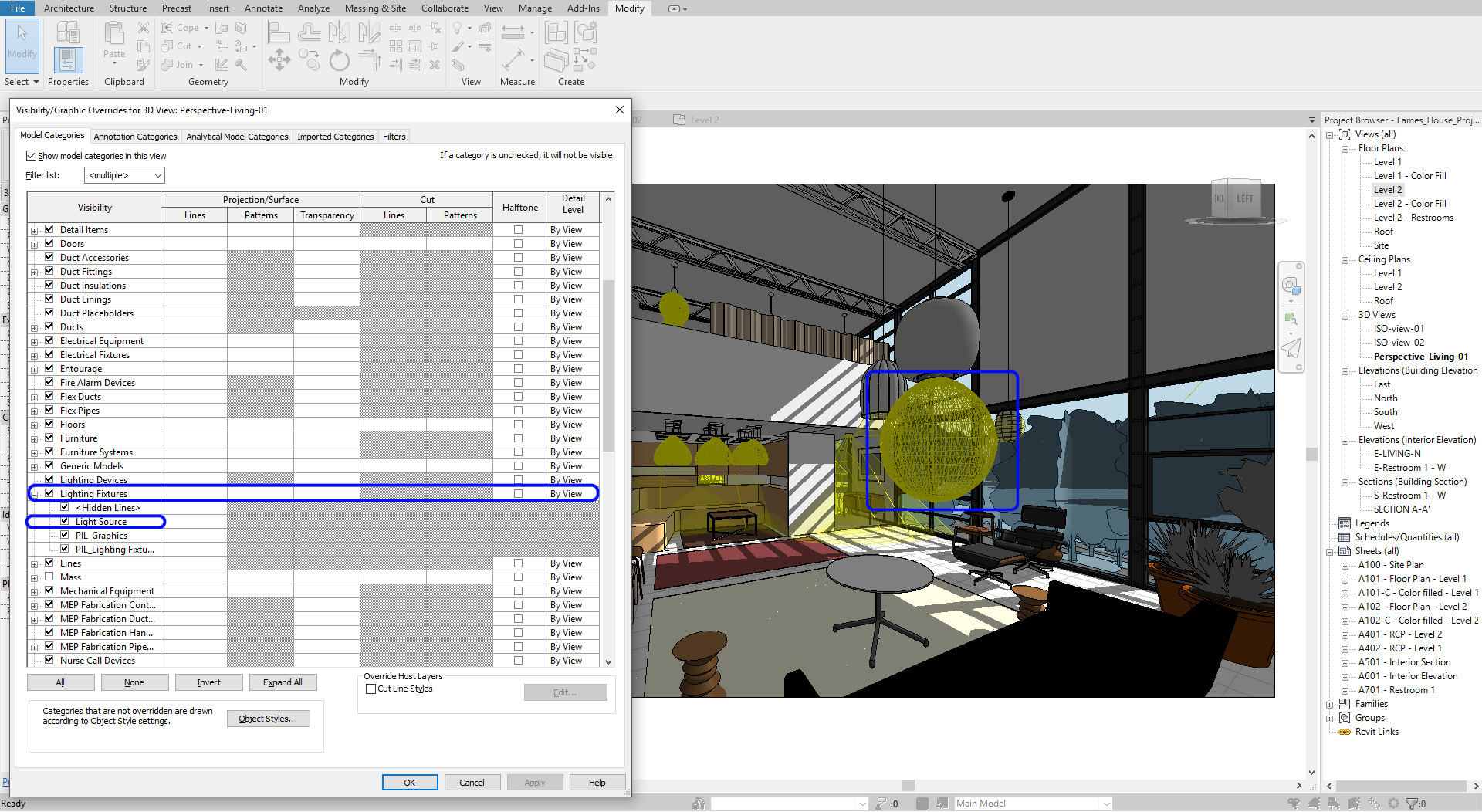
- [STEP 2] Open Visibility/Graphics Overrides, or type [VV] for 3D view
- [STEP 3] Turn on Lighting Source to see the light source
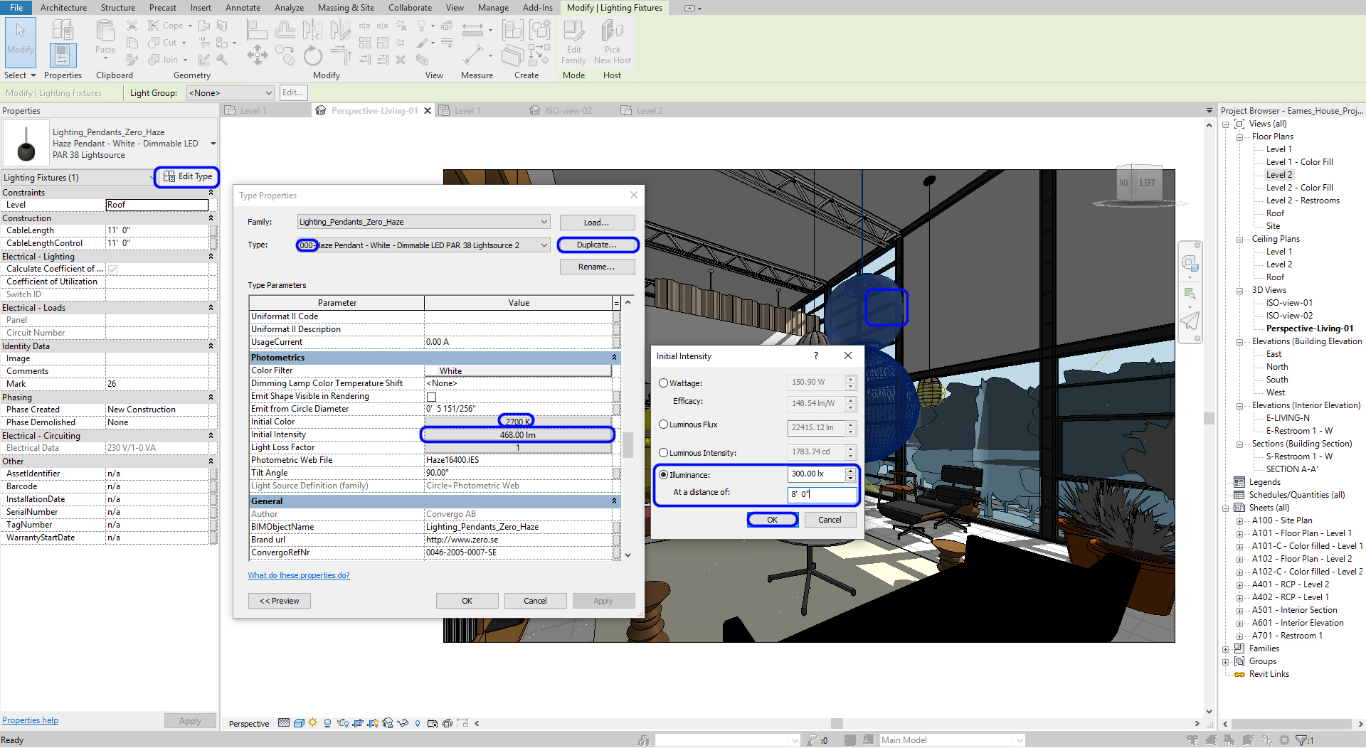
Lighting setting
- [STEP 1] Click the lighting fixture that you want to modify
- [STEP 2] Click Edit Type > Click Duplicate and name the new type
- [STEP 3] Modify Photometrics [initial intensity] > I recommend to adjust the value of [Illuminance] and [at a distance of]
Please refer to this page for the recommended lighting level (Lux) for activities Repeat this step for all other lighting sources
- [STEP 4] Test render to see if the light fixtures are at the right setting.
-
Recessed indirect lighting
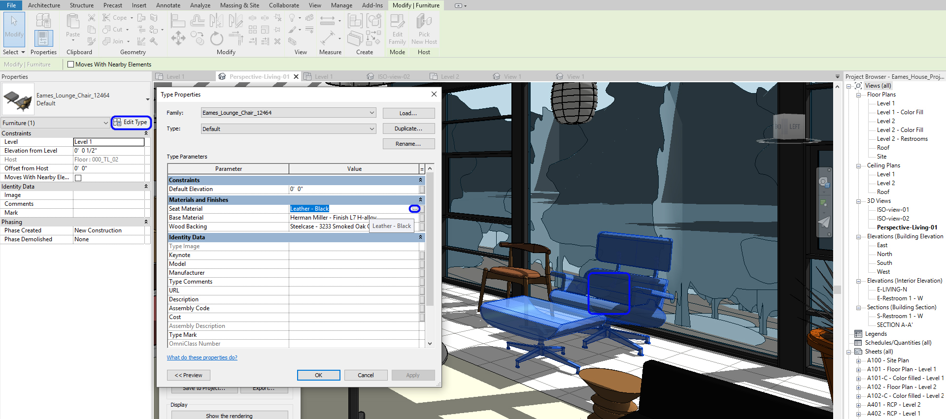
(CO 7) Add/Edit materials
Apply materials in Family type
- [STEP 1] Click an object that you want to add or change materials
- [STEP 2] Click [Edit Type] to change Materials and Finishes
- [STEP 3] Duplicate if needed
- [STEP 4] Click Material Value (Not all objects have this option, but many family files do this option) to add or modify the material. Then Material Browser will pop up
- [STEP 5] If you already made a material you want to use, please select the material and click ok to finish
- [STEP 6] If you want to make a new material, click Create New Material
- [STEP 7] Mouse right-click and click to [Rename] the new material [Ex. 000-FB-01-White]
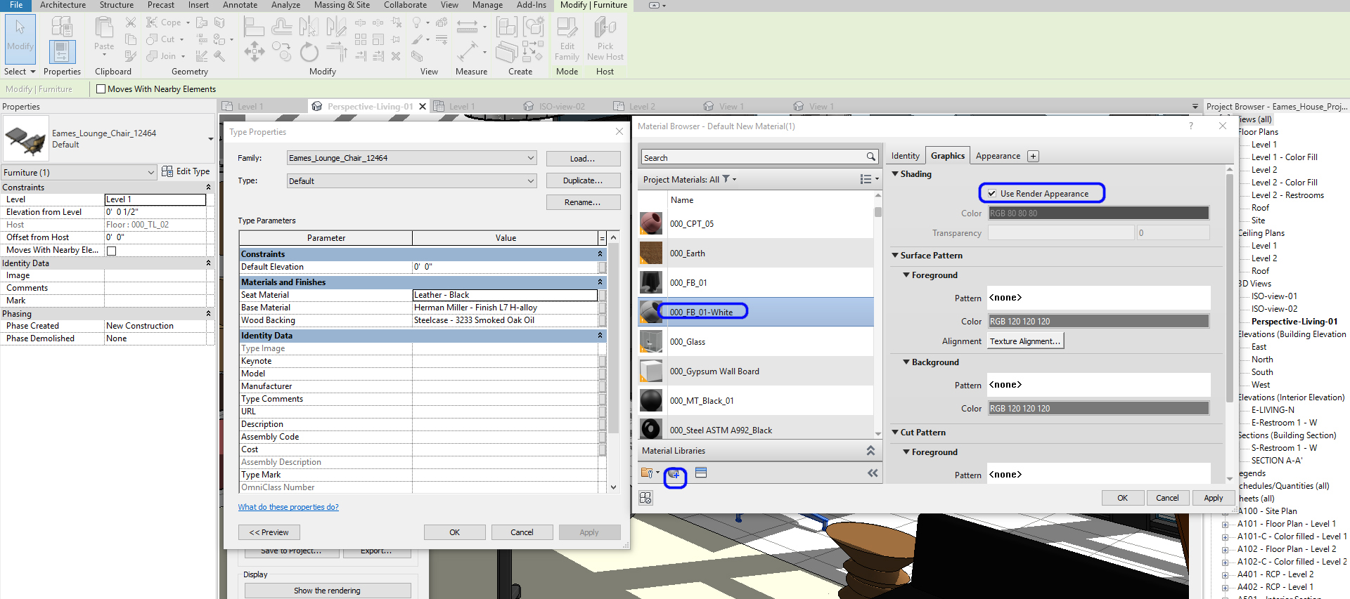
- [STEP 8] You can change Identity, Graphics, and Appearance. To add material from Revit Library, click Appearance, Click [Replace] this Asset. Asset Browser will pop up
- [STEP 9] Search a material from Appearance Library
- [STEP 10] Click a replace icon
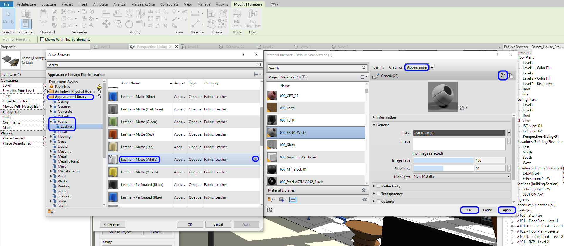
- [STEP 11] Click Information, name change if this is a unique material
- [STEP 10] Click ok to apply
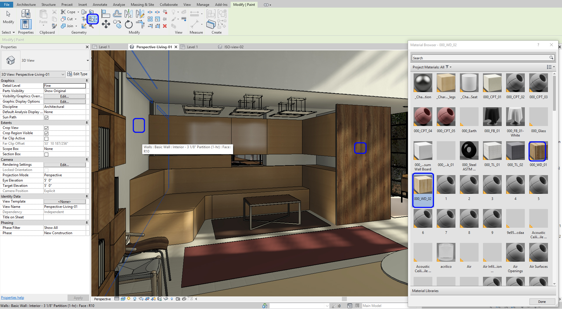
Painting materials (For Walls, Floors, and Ceilings)
- [STEP 1] To use [Paint] tool, click [Paint] from the [Modify] tab
- [STEP 2] Click a material that you want to use from Material Browser. If you do not find the material that you want to use in the Material Browser, you must add a new material first and then apply the paint tool
- [STEP 3] Click a face that you want to change, use the Tab key to select right face
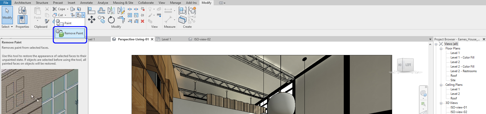
- [STEP 4] You also can remove the paint material by using the Remove Paint tool
- [STEP 5] Use [Split Face] (If the surface needs to be separated), Click [Split Face] from [Modify] tab
- [STEP 6] Click the elements (Wall, Floor, Ceiling) you want to split face. You may need to use the TAB key to select the elements
- [STEP 7] Draw a closed line to divide the surface. You may need to open an elevation view, a floor plan, or a ceiling plan to draw the lines.
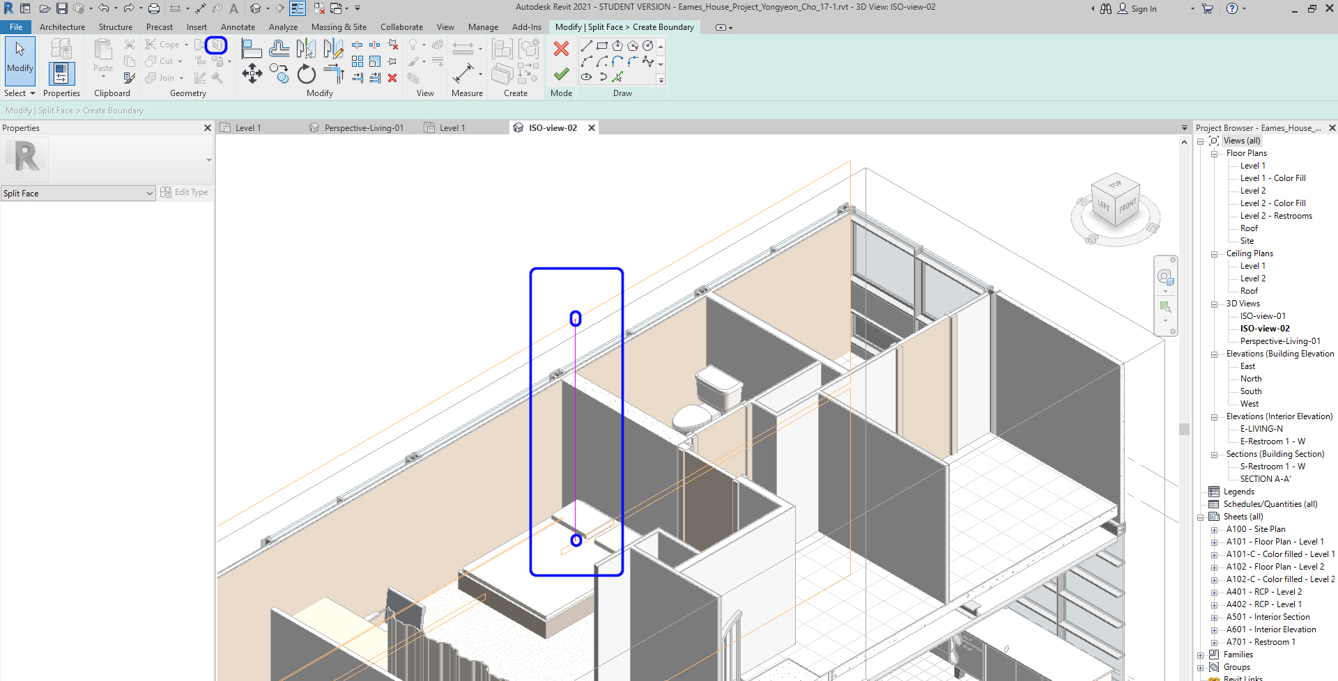
- [STEP 8] Click Green checkmark to finish
- [STEP 9] Then use the Paint tool to apply the material
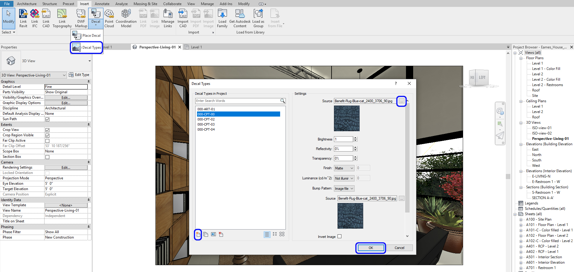
Decal (Flat Surface – Carpet or pictures)
- [STEP 1] To create Decal, click Decal Types from the Insert tab
- [STEP 2] Please create a new Decal, Name it, insert the image, and click ok
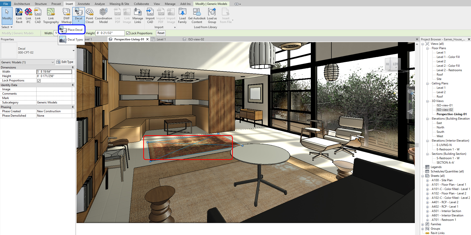
- [STEP 3] To place a Decal, Click Place Decal from the insert tab
- [STEP 4] Place on a surface
- [STEP 5] Change size and location from views
(CO 8) Render material managements
Manage material
- [STEP 1] Click [Materials] from [Manage] tab
- [STEP 2] In this [Material Browser], you can add and modify materials
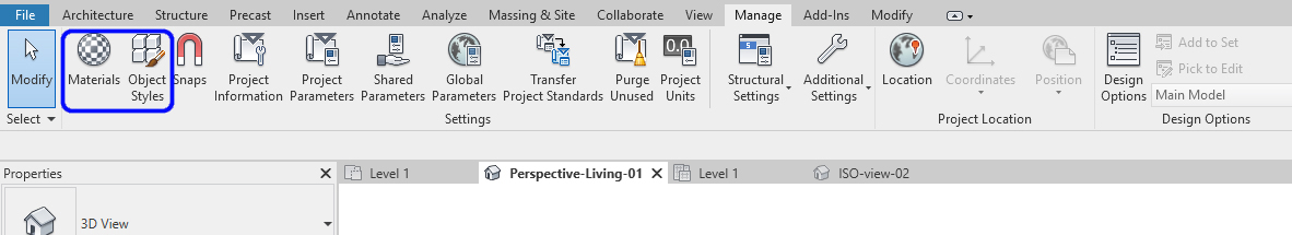
- [STEP 3] If you need to apply an imported object (CAD or Sketchup), use [Object Styles]
SAVE the file before closing the application.
Save in a different location for the backup (e.g., a cloud folder)
 References
Autodesk.Help. (2019, November 17). 3D Views. Retrieved October 22, 2020, from https://knowledge.autodesk.com/support/revit-products/learn-explore/caas/CloudHelp/cloudhelp/2020/ENU/Revit-DocumentPresent/files/GUID-B3354433-8ED8-4DA7-8078-C2514195BEB5-htm.html
Airfal. (2014, January 15). Recommended light levels for common types of working activities. Retrieved October 23, 2020, from https://www.airfal.com/en/industrial-lighting/recommended-light-levels-common-types-of-working-activities-2875/
Balkan Architect. (2018, January 3). Recessed Ceiling with Light in Revit * Light Tutorial*. Retrieved October 23, 2020, from https://www.youtube.com/watch?v=4VFK-KEOMZc
