
Part One. AutoCAD
Chapter 2. Draw floor plans
Upon completing this session, students will be able to:
- (CO 1) Understand Layers – Name, Line type, Thickness, & Color
- (CO 2) Draw centerlines – Object snap, Line, Move, & Offest
- (CO 3) Draw exterior/interior walls, floor, millwork & openings – Polyline, Spline, Circle, Rectangle, Object Snap, Mirror, Fillet, Trim, Extend, Array, & Match Properties
 Session Highlights
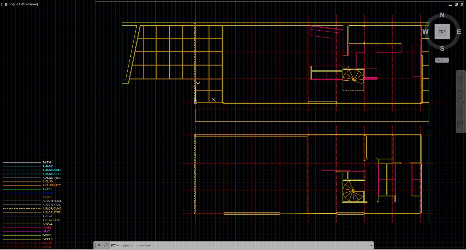
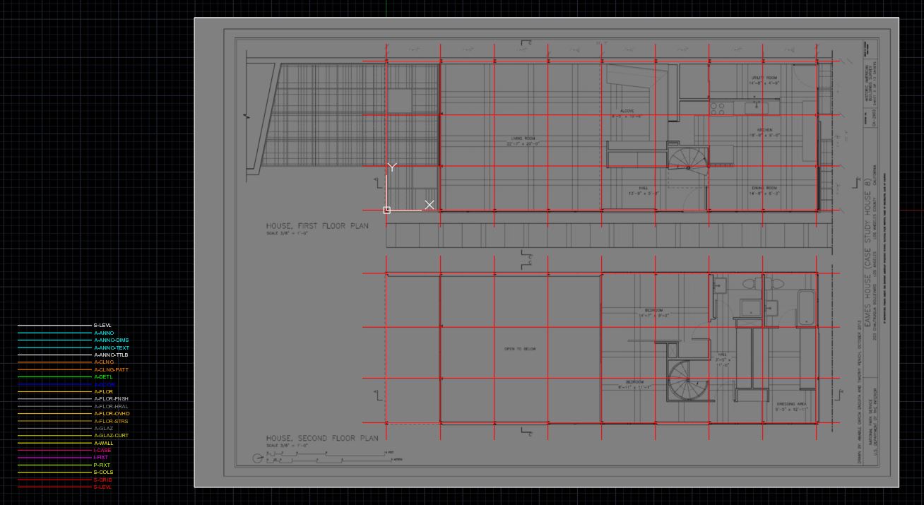
At the end of the session, students can create the graphics below.
 Lecture Contents
(CO 1) Understand Layers – Name, Line type, Thickness, & Color
The concept of layers in CAD
Architects and designers use layers in vector-based CAD software.
The concept of layers allows CAD information to be organized, facilitates the visual display of the information on a computer screen, and allows the information to be efficiently converted to the conventional print media of drawings.
The efficient use of layers can reduce document preparation time and improve document coordination.
The American Institute of Architects and National Cad Standard published “AIA CAD Layer Guidelines.”
Using layers can make your drawings easier to control and interpret for both you and your team. For example, you can draw your interior walls on one layer, and furniture on another using a different color. You can quickly turn off your furniture layer on a floor plan and turn on the furniture layer on a furniture plan.
You can control layers from the Layer Property Manager.
Each layer has a set of properties assigned to it.
- Name
- Turn On/Off
- Freeze – Looks the same as turning on and off but uses less memory. Boost the speed of work.
- Lock
- Plot – It shows on your screen, but it will not print.
- Color – It is for working on the screen – easier to recognize the layers by color. Usually, prints in black and white.
- Line weight – Important to identify the hierarchy of the lines
- Line type
- Transparency – not often used
- Description – note for the layer
Create Layers for the project
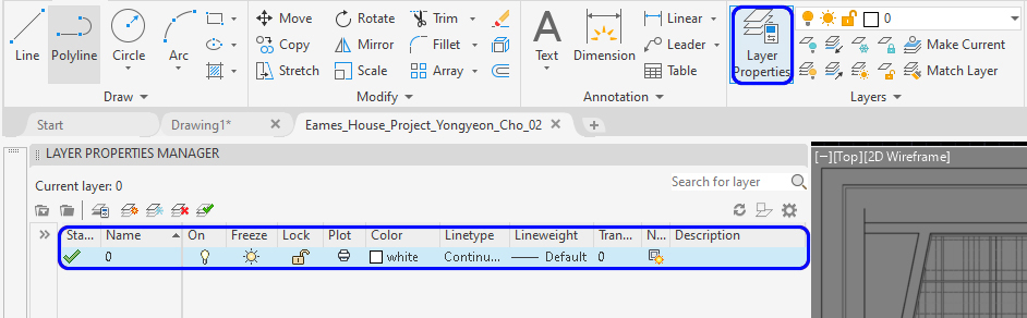
- [STEP 01] Open the Layer Property Manager panel by clicking the [Layer Property] icon under the [Home] tab on the [Layers] panel.
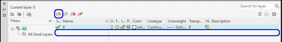
- [STEP 02] Click [New Layer] or Press [Alt+N] to add a new layer
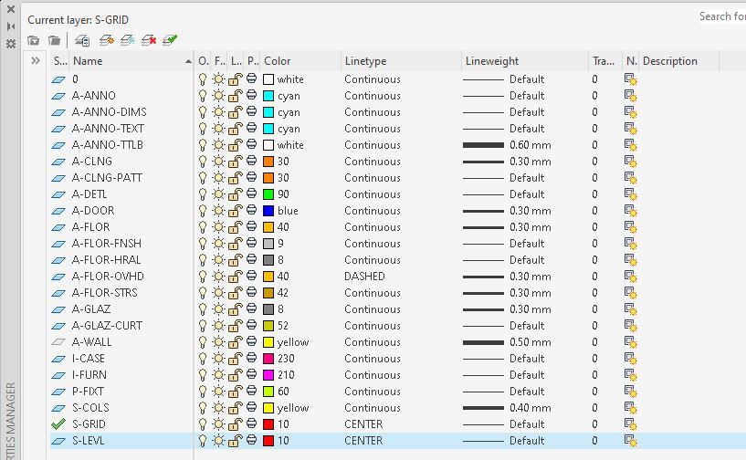
- [STEP 03] Rename the name of the layer by double-clicking the name of the layer to A-WALL
- [STEP 04] Update the color of the layer by clicking the color section to YELLOW
- [STEP 05] Update the line weight of the layer by clicking the Lineweight section to 0.5
- [STEP 06] Repeat the [STEP 02] to [STEP 05] to create the listed Layers below.
Note 1. To update line type, click the line type that you want to update, and click [LOAD], and find the line type that you want to use for a layer, and click [OK], click the loaded line type to apply, and click [OK] to apply.
Note 1A. Due to the scale issue, the line type will not show it correctly. To correct the line type scale, type [lts] on the keyboard, and press the [Enter] key and enter [number]. For this project, try [10]
Note 2. The name of the layer is based on AIA CAD layer guidelines, the instructor modified. If you need other layers, please refer to the guideline.
Apply a layer to a model
[Method 1]
- [STEP 01] Fine a line/lines or an element/elements that you want to apply a layer
- [STEP 02] Select a layer that you want to apply to, then a layer of the element will be changed
[Method 2]
- [STEP 01] Select a layer that you want to draw
- [STEP 02] Draw a line/lines or an element/elements within the layer
[Method 3]
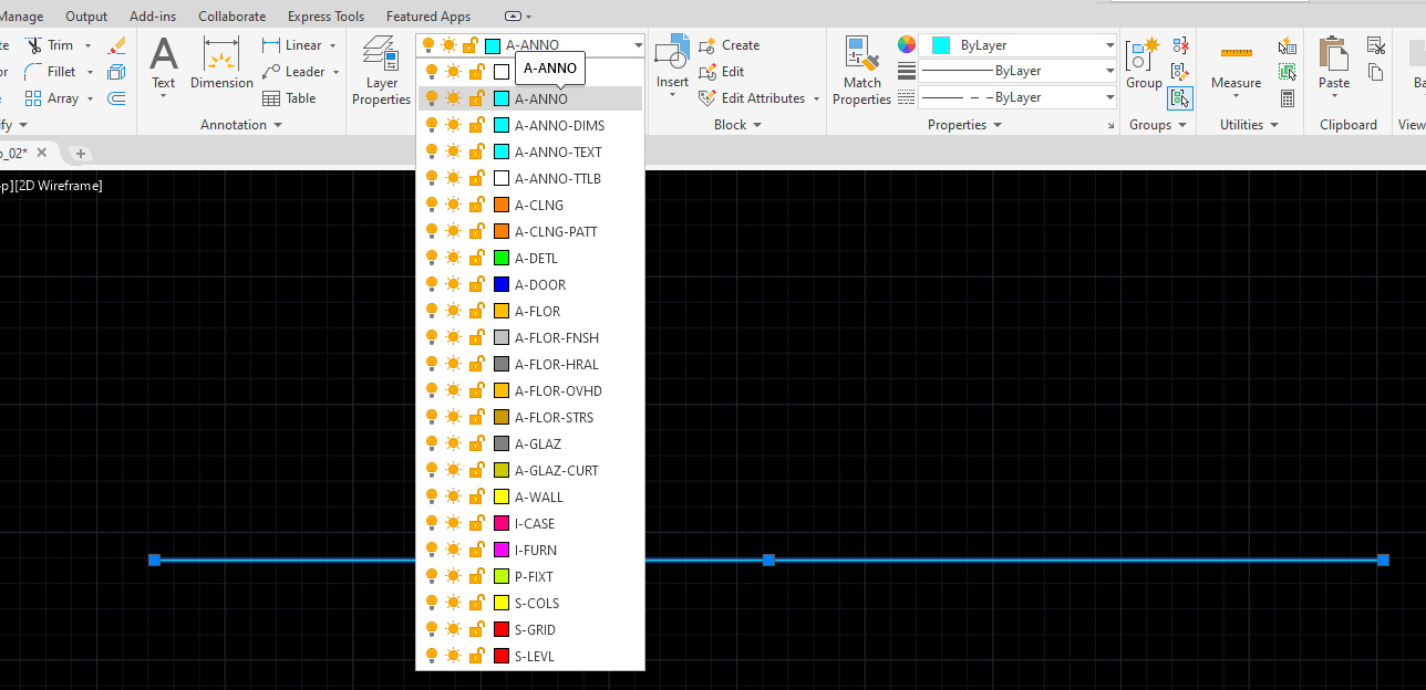
- Use [MATCHPROP] command or [MA] – match the property to copy a layer style to another
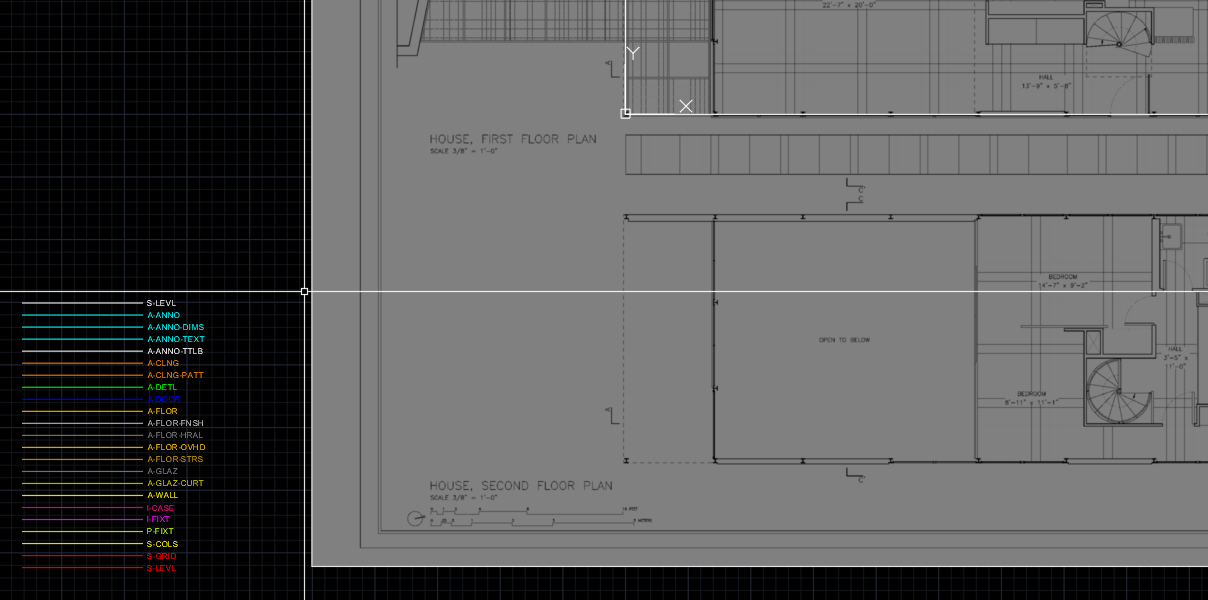
Tip. I prefer to use this method to speed up the work – Draw lines with all layers with name on the side of the drawing, and use match property command whenever it is needed. You can save time to find the layer and select the layer from the drop-down menu.
(CO 2) Draw centerlines-column grid – Object snap, Line, Move, & Offset
Drawing a centerline can be the first step in drawing a floor plan. The drawing order depends on the phase of design and who is drawing. However, setting centerlines can be easier to draw a floor plan rather than starting from scratch.
- [STEP 01] Select the right layer to draw column grids. Click [S-GRID] from the [Home] ribbon on the [Layers] tab
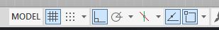
- [STEP 02] Make sure [othormode] and [osnap] is on
OSNAP setting – to select a specific point of an element, it is recommended to use object snap [OSNAP]. To set up object snap, mouse right click on the OSNAP icon on the Status bar and check the point that you would like to select while the object snap is on.
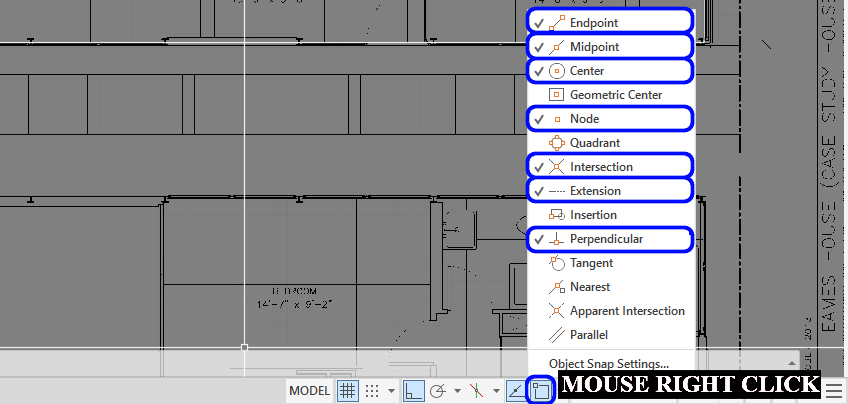
This image is the recommended object snap settings for 2D drafting, based on the instructor’s experience. Note. For more information regarding OSNAP, please read this link about using Object Snapes.
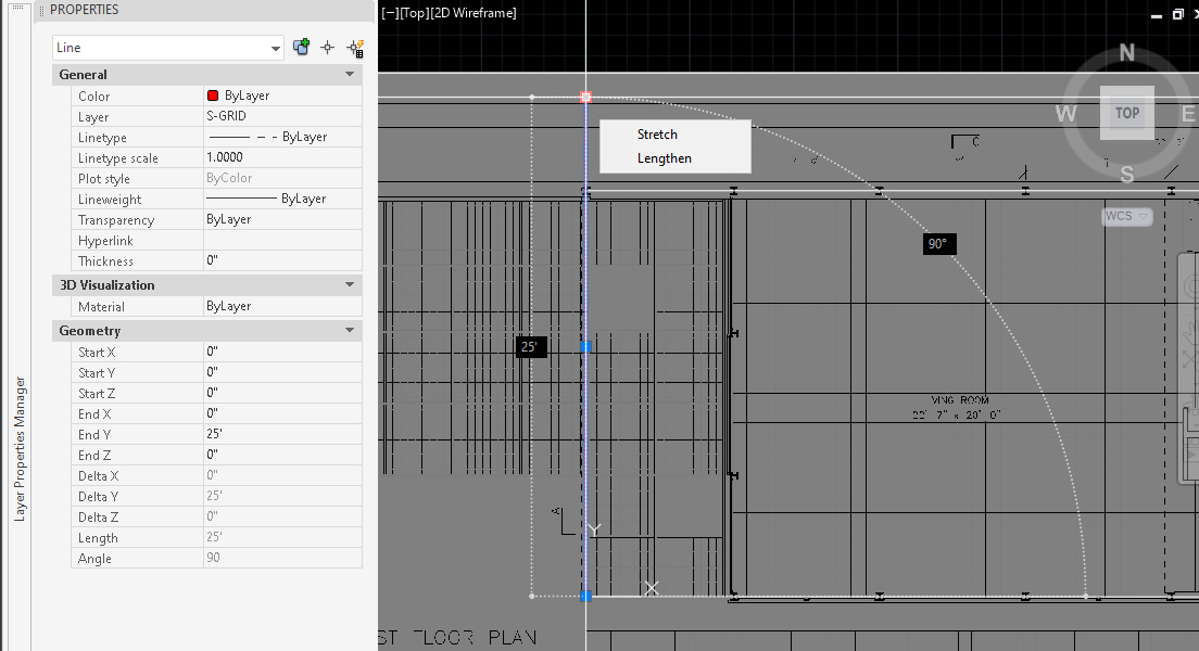
- [STEP 03] Select [Line] from [Home] ribbon on [Draw] tab ,or Type [l] and press [Enter] on the keyboard to draw lines
Click the base point [0,0] and mouse move to plan north, and type [25′] and press [Enter] on the keyboard
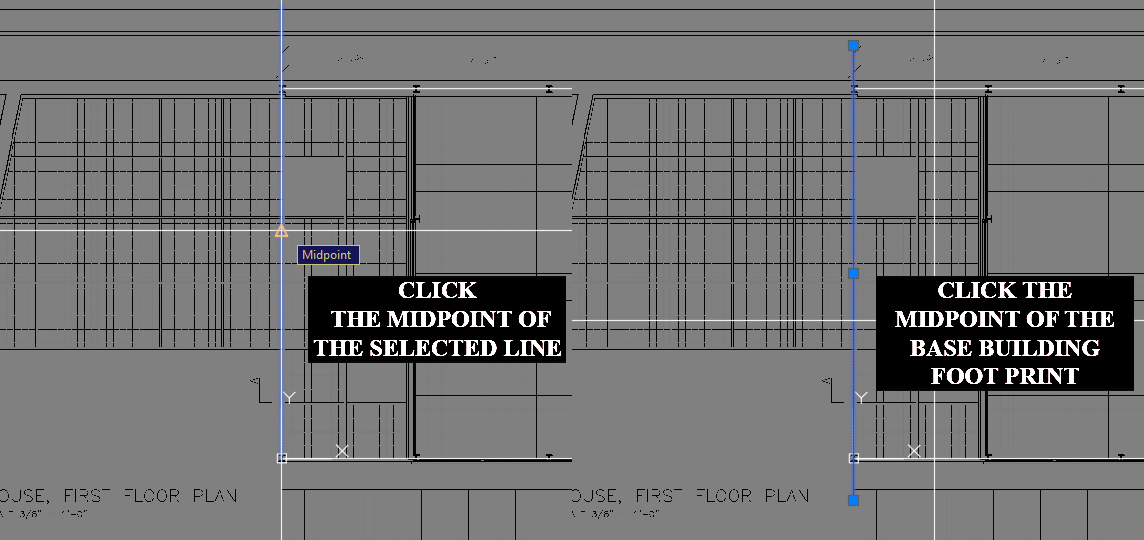
- [STEP 04] Move the gridline to the center of the building base footprint.
Click [Move] icon from [Home] ribbon on [Draw] tab
or, type [m] and press [Enter] key
Click the midpoint of the selected line, and then click the midpoint of the building footprint
- [STEP 05] To create vertical grid lines, it is recommended to use the [OFFSET] command.
Click [OFFSET] icon from [HOME] ribbon on [DRAW] tab
or, type [o] and press [Enter] key
Type a specific number that you want to offset, for this project, enter 7′-4-3/4″
and then press [Enter] key,
and then click a point to the direction that you want to create the copied line,
if you use the same distance, you do not need to enter the number,
if you use a different distance, you must enter a specific number - [STEP 06] Repeat [STEP 03] to [STEP 05] for horizontal grid lines
- [STEP 07] Copy the first level grid lines, both vertical and horizontal, for the second level
To copy the lines, please use an even number (e.g., 28′-11″ based on the base drawing)
(CO 3) Draw exterior/interior walls, floor, millwork & openings – Polyline, Spline, Circle, Rectangle, Mirror, Fillet, Trim, Extend, Array, & Match Properties
Let’s draw the floor plans (no columns, no furniture, no windows, no doors, no patterns, no symbols, no plumbing, no dimensions, no texts at this point) with the following commands
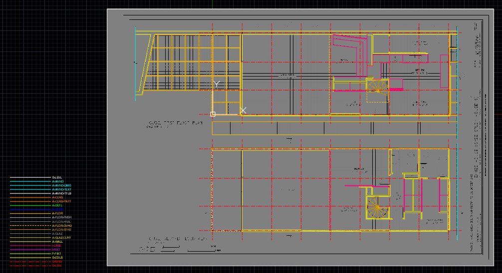
image credit: Screen captured by the Author from the application
Make sure you use the commands below to control and easy selection
[ORTHO] or [F8] key, [OSNAP] or [F3] key
If needed, you can turn on/off [grid] by press the [F7] key
Polyline(command) – this is for creating a connected line. Once you make an element (wall) with a polyline, the lines will be connected. This connection is useful in controlling each element.
- [STEP 01] Type [pl] on keyboard and press [Enter] key
- [STEP 02] Specify start point
- [STEP 03] Specify the next point.
- [STEP 04-01] If you want to close the object, type [c] on the keyboard and press the [Enter] key
- [STEP 04-02] If you want to finish the object without closing the object, press the [ESC] key
- Please refer to this link for the polyline command
Pedit(command) – this used to convert line objects to a polyline
- [STEP 01] Type [pe] on keyboard and press [Enter] key
- [STEP 02] Specify an object to convert a polyline
- [STEP 03] Type [y] and press the [Enter] key to turn the objects into one object.
- [STEP 04] Select [Join]
- [STEP 05] Select all connected objects that you want to join as a polyline, and press [Enter] key, and press [Enter] key one more time to finish the command
- Please refer to this link for the Pedit command
Explodes(command) – this is to convert a polyline or a block to line objects
- [STEP 01] Select an object (polyline or a block) to convert to line objects
- [STEP 02] Type [x] on the keyboard, and press [Enter] on the keyboard
- Please refer to this link for the Explodes command
Spline(command) – may not be needed for the Eames House project, but you will need it for your project – These commands for creating a connected curved line.
- [STEP 01] Type [spl] on keyboard, and press [Enter] key
- [STEP 02] Specify the first point
- [STEP 03] Specify the next points
- [STEP 04] Press [Enter] key to finish
- Please refer to this link for the Spline command
Circle(command)
- [STEP 01] Type [c] on keyboard, and press [Enter] key
- [STEP 02] Specify a center point
- [STEP 03] Specify a radius by typing a specific number of by clicking a specific point
- Please refer to this link for the circle command
Rectangle(command)
- [STEP 01] Type [rec] on keyboard, and press [Enter] key
- [STEP 02] Specify a first corner point
- [STEP 03] Specify another corner point
- Please refer to this link for the Rectangle command
Mirror(command)
- [STEP 01] Type [mi] on keyboard, and press [Enter] key
- [STEP 02] Select an object/objects, and press [Enter] key
- [STEP 03] Specify the first point of the mirror line
- [STEP 04] Specify the second point of the mirror line
- [STEP 05] Decide whether to erase the source objects or not, and press the [Enter] key to complete the command
- Please refer to this link for the Mirror command
Fillet(command) – create a corner between two objects
- [STEP 01] Type [f] on keyboard, and press [Enter] key
- [STEP 02] Select the first object
- [STEP 02-01] If you want to create a smooth corner, you can specify radius by type [r] and press [Enter] key, and type [specific number] and press [Enter] key
the radius information will be stored, if you want to create a sharp corner, the R = ‘0.’ - [STEP 03] Select the second object
- Please refer to this link for the Fillet command
Trim(command)
- [STEP 01] Type [tr] on keyboard, and press [Enter] key
- [STEP 02] Select cutting edges
- [STEP 03] Select object(s) to trim, and press the [Enter] key to complete the command
- Please refer to this link for the Trim command
Extend(command)
- [STEP 01] Type [ex] on keyboard, and press [Enter] key
- [STEP 02] Select boundary object(s)
- [STEP 03] Select object(s) to extend, and press the [Enter] key to complete the command
- Please refer to this link for the Extend command
Stretch(command)
- [STEP 01] Type [s] on keyboard, and press [Enter] key
- [STEP 02] Select objects – specify the portion of the object that you want to stretch, using the crossing object selection method, and press [Enter] key
- [STEP 03] Specify the base point
- [STEP 04] Specify the destination point to complete the command
- Please refer to this link for the Stretch command
Match Property(command)
- [STEP 01] Select source object
- [STEP 02] Select destination object(s)
- Please refer to this link for the Match Property command
There is no right or wrong way to draw a floor plan, be creative, Designers!!
SAVE the file before closing the application.
Save in a different location for the backup (e.g., a cloud folder)
 References
National Institute of Building Sciences. (2005). AIA CAD Layer Guidelines: U.S. National CAD Standard Version 3. Retrieved October 12, 2020, from http://www.close-range.com/docs/US_National_CAD_Standard_V3.pdf
Autodesk Help. (2020, May 29). About Using Object Snaps. Retrieved October 13, 2020, from https://knowledge.autodesk.com/support/autocad/learn-explore/caas/CloudHelp/cloudhelp/2020/ENU/AutoCAD-Core/files/GUID-8F5E5431-9EFB-414E-BC6D-2C65EFB2DAC3-htm.html
Autodesk Help. (2020, May 29). PLINE (Command). Retrieved October 13, 2020, from https://knowledge.autodesk.com/support/autocad/learn-explore/caas/CloudHelp/cloudhelp/2020/ENU/AutoCAD-Core/files/GUID-11883C70-6435-4F80-8FB4-F6E933B8FD94-htm.html
Autodesk Help. (2020, May 29). PEDIT (Command). Retrieved October 13, 2020, from https://knowledge.autodesk.com/support/autocad/learn-explore/caas/CloudHelp/cloudhelp/2020/ENU/AutoCAD-Core/files/GUID-0C422AA9-23DD-4650-AD66-68E9D7989E3F-htm.html
Autodesk Help. (2020, May 29). EXPLODE (Command). Retrieved October 13, 2020, from https://knowledge.autodesk.com/support/autocad/learn-explore/caas/CloudHelp/cloudhelp/2020/ENU/AutoCAD-Core/files/GUID-E98BCEF4-DED6-48A6-87EB-10FE87188083-htm.html
Autodesk Help. (2020, May 29). SPLINE (Command). Retrieved October 13, 2020, from https://knowledge.autodesk.com/support/autocad/learn-explore/caas/CloudHelp/cloudhelp/2020/ENU/AutoCAD-Core/files/GUID-5E7D51E2-1595-4E0C-85F8-2D7CBD166A08-htm.html?v=2020&st=spline
Autodesk Help. (2020, May 29). CIRCLE (Command). Retrieved October 13, 2020, from https://knowledge.autodesk.com/support/autocad-lt/learn-explore/caas/CloudHelp/cloudhelp/2020/ENU/AutoCAD-LT/files/GUID-C60B6D5D-AAEB-420F-917F-6E6B47E92F48-htm.html
Autodesk Help. (2020, May 29). RECTANG (Command). Retrieved October 13, 2020, from https://knowledge.autodesk.com/support/autocad/learn-explore/caas/CloudHelp/cloudhelp/2020/ENU/AutoCAD-Core/files/GUID-188B2DDA-6CD8-4D37-BF26-E6CF27C34C75-htm.html
Autodesk Help. (2020, May 29). MIRROR (Command). Retrieved October 13, 2020, from https://knowledge.autodesk.com/support/autocad/learn-explore/caas/CloudHelp/cloudhelp/2020/ENU/AutoCAD-Core/files/GUID-595277C8-9B87-4CFB-A3AF-769537A22F3D-htm.html
Autodesk Help. (2020, May 29). FILLET (Command). Retrieved October 13, 2020, from https://knowledge.autodesk.com/support/autocad/learn-explore/caas/CloudHelp/cloudhelp/2020/ENU/AutoCAD-Core/files/GUID-64F8B700-23B3-4BD6-8C03-66121AA13E8F-htm.html
Autodesk Help. (2020, May 29). TRIM (Command). Retrieved October 13, 2020, from https://knowledge.autodesk.com/support/autocad/learn-explore/caas/CloudHelp/cloudhelp/2020/ENU/AutoCAD-Core/files/GUID-B1A185EF-07C6-4C53-A76F-05ADE11F5C32-htm.html
Autodesk Help. (2020, May 29). EXTEND (Command). Retrieved October 13, 2020, from https://knowledge.autodesk.com/support/autocad/learn-explore/caas/CloudHelp/cloudhelp/2020/ENU/AutoCAD-Core/files/GUID-89DD7B0F-F4F1-410D-9A3A-5847CA5F8744-htm.html
Autodesk Help. (2020, May 29). STRETCH (Command). Retrieved October 13, 2020, from https://knowledge.autodesk.com/support/autocad/learn-explore/caas/CloudHelp/cloudhelp/2020/ENU/AutoCAD-Core/files/GUID-F000A502-D39E-4D31-A8E2-4A626473FB72-htm.html
Autodesk Help. (2020, May 29). MATCHPROP (Command). Retrieved October 13, 2020, from https://knowledge.autodesk.com/support/autocad/learn-explore/caas/CloudHelp/cloudhelp/2020/ENU/AutoCAD-Core/files/GUID-BD476C7C-2CA4-4FB2-8A9E-EAAD5A072445-htm.html
