
Part One. AutoCAD
Chapter 1. Introduction of AutoCAD
Upon completing this session, students will be able to:
- (CO 1) Understand what is the application & 4 different AutoCAD
- (CO 2) Install the application on your computer
- (CO 3) Understand the User Interface of AutoCAD – Ribbon, Panels, Model space, Layout tabs, Status bar, & Properties
- (CO 4) Understand AutoCAD setup tips – Options, Units, Workspace
- (CO 5) Understand the types and structure of drawings in Auto CAD- Floor plan, RCP, Elevation, Section, & Details
- (CO 6) Input commands and understand different selections
- (CO 7) Understand basic drawing tools- Origin, Rectangle
- (CO 8) Attach image/PDF/CAD and adjust the scale
- (CO 9) Set the project folder, Save the file, and backups
 Session Highlights
At the end of the session, students can create the graphics below.
 Lecture Contents
(CO1) Understand what is the application & 4 different AutoCAD
About CAD
Computer-Aided Design(CAD) or Computer-Aided Design and Drafting (CADD) can be defined as using computer systems to assist in the creation, modification, analysis, or optimization of a design. (Narayan, 2008)
CAD software is used to increase the productivity of the designer, improve the quality of design, improve communications through documentation, and create a database for manufacturing. (Narayan, 2008)
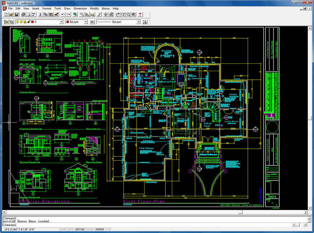
image credit: Shaan Hurley, AutoCAD R14 Welcome Sample DWG, Flicker
CAD is an important industrial art extensively used in many applications, including automotive, shipbuilding, and aerospace industries, industrial and architectural design, prosthetics, and many more. (Pottmann, and et al., 2007)
About AutoCAD
AutoCAD is an industry-leading commercial CAD software.
AutoCAD is used by AEC(Architecture, Engineer, and Construction) to generate and optimize 2D and 3D designs. AutoCAD is a widely used software program that can help you draft construction documentation, explore design ideas, visualize concepts through photorealistic renderings, and simulate how a design performs in the real world. (Autodesk)
AutoCAD was first released in December 1982 as a desktop app. In 2010, AutoCAD was released as a mobile- and web app, marketed as AutoCAD 360. (Autodesk and AutoCAD)
Four AutoCAD products for AEC
- AutoCAD: the original version of AutoCAD. This version can use architects, project managers, engineers, graphic designers, city planners, and other professionals.
- AutoCAD Architecture: a version of Autodesk’s flagship product, AutoCAD, with tools and functions specially suited to architecture work. This software supports dynamic elements (wall, door, windows, and other architectural elements) and automatically updating Spaces and Areas for calculations of sqft.
- AutoCAD LT: the lower-cost version of AutoCAD, with reduced capabilities (No 3D, No Network Licensing, No management tools, and more).
- AutoCAD 360: an account-based mobile and web application enabling registered users to view, edit, and share AutoCAD files via a mobile device and web using a limited AutoCAD feature set and using cloud-stored drawing files.
(CO2) How to install the application
Install AutoCAD
This version is for educational purposes only.
You must know your system requirement first before you install the application. If you do not know your system use, please find the information here.
- [STEP 01] Go to https://www.autodesk.com/education/free-software/autocad on your Windows side, open a web browser (Chrome is recommended because the instructor tested).
- [STEP 02] Click [CREATE ACCOUNT] if you do not have one. If you already have an Autodesk account, please sign in by clicking [SIGN IN].
- [STEP 03] Select an appropriate version of AutoCAD, your system, and language.
- [STEP 04] Click [INSTALL].
- [STEP 05] Accept the license and services agreement.
- [STEP 06] You will receive an email from Autodesk for the license information (Product key and Serial Number). It will be needed for the activation process.
- [STEP 07] Click the downloaded installation file to install. The installation will take a while.
- [STEP 08] After installation, the software will require activation. Please use the license information.
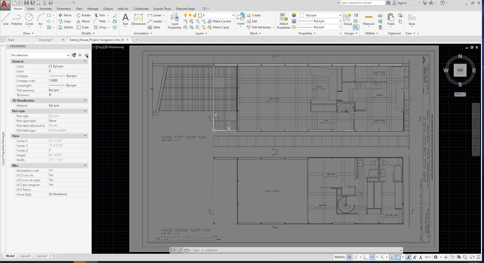
(CO3) Understand AutoCAD interface – Ribbon, Panels, Model space, Layout tabs, Status bar, & Properties
Once you open AutoCAD by double-clicking the AutoCAD icon, you can create a new drawing by clicking the [START DRAWING] icon on the first page of the AutoCAD application.
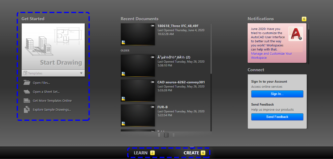
You also can select a different template by clicking [TEMPLATES] under start drawing. The default setting is [acad.dwt]
Your recent documents will show in the middle of the first page. You also can click to open the recent documents.
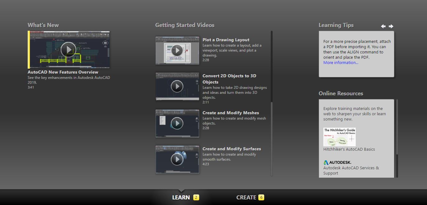
For the tutorial provided by Autodesk, you can click [LEARN]. I recommend you watch the Getting Started Videos.
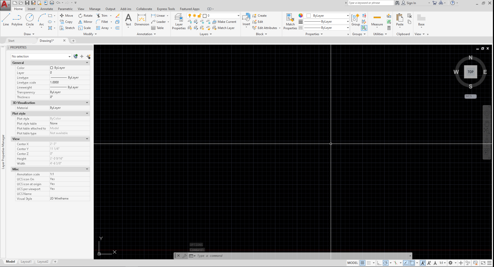
Once you click [START DRAWING], you will see this user interface below. [please remember the names]
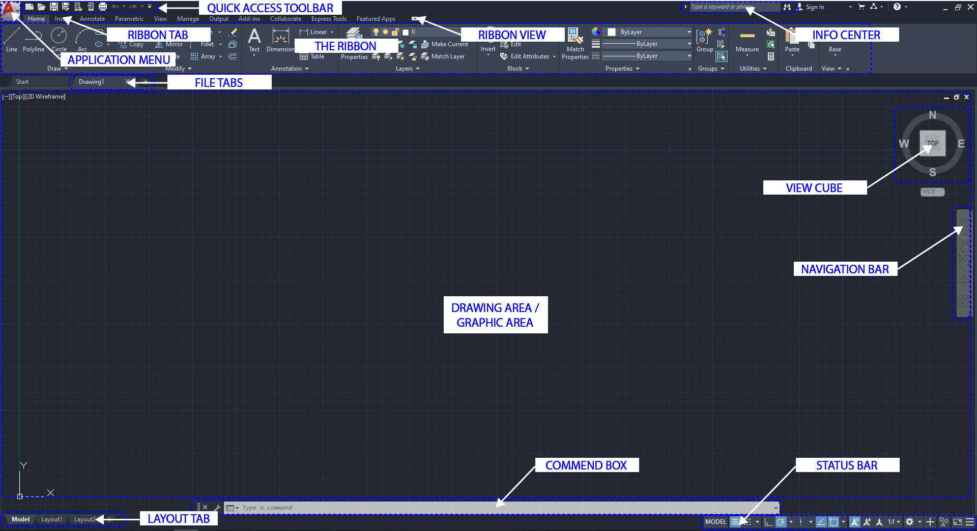
- Application menu: New, open, save, import, export, print
- Quick access toolbar: User can save tools that they often use
- Info Center: Ask a question, find out answers from Autodesk community
- Ribbon: Main menus – Home, Insert, Annotate, View, Manage
- Ribbon tab
- Ribbon view: User can minimize and maximize the ribbon
- File tab: Navigate files and create and open files
- Drawing area/graphic area: Main drawing space
- View cube: User can change the view, top, front, 3D, or more
- Navigation bar: Zoom in and out, pan, zoon to all, and more
- Command box: Can type commands and see the previous commands
- Layout tab: Can see model space and print spaces
- Status bar: Can set grid, snaps, scales, and more
Please see this detailed user interface that is provided by Autodesk
(CO4) AutoCAD setup tips – Options, Unites, Workspace
Before you start your drafting, it is recommended to set your workspace and options as you wish. Take some time and experiment with the settings, as shown below. You can change settings at any time.
Below are the instructor’s recommended setups based on more than 10-years of drafting experience.
OPTIONS
- [STEP 01] Click [APPLICATION MENU] and then Click [OPTIONS], or type [options] on the command box, and Enter key
- [STEP 02] You will see the Option window
- [STEP 03] Click Display tab > Change Color theme from dark to light
- [STEP 04] Find Crosshair size on the Display tab > Change the value from 5 to 100
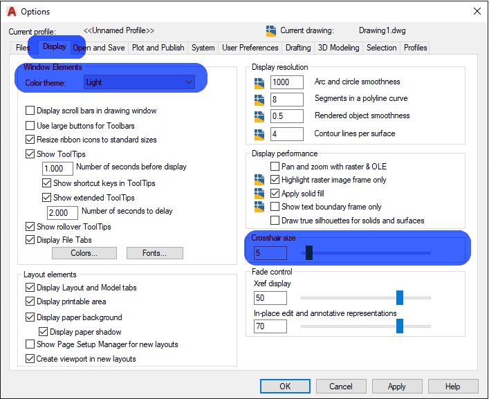
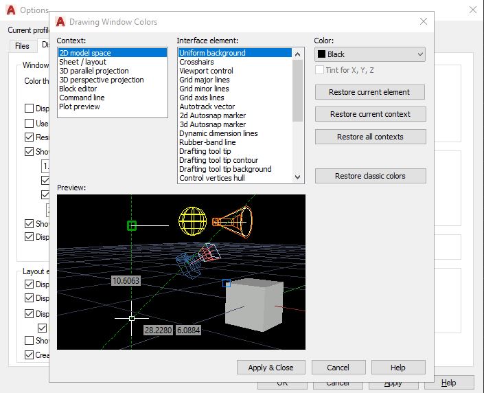
- [STEP 05] Find [Colors] and change Uniform background to Black> Click [Apply & Close]
- [STEP 06] Click the Draftingtab > Change the aperture size – make slightly smaller
- [STEP 07] Click the Selection tab and uncheck[allow the press and drag for lasso] > Click [OK] to close the option
![Option selection setting - It shows an additional setting for selecting strategy. Uncheck [Allow press and drag for lasso]](https://iastate.pressbooks.pub/app/uploads/sites/50/2020/09/01_03_06_Option_Selection_01-1.jpg)
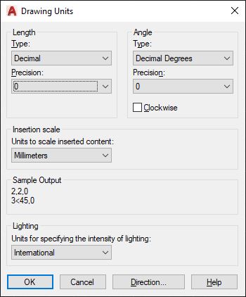
UNITS
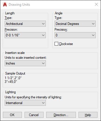
- [STEP 01] Click [APPLICATION MENU] > click [DRAWING UNITS] > click [UNITS] or, Type [units] on the command box > Enter key
- [STEP 02] Confirm the units are right for your project
Below snap is an image of a typical setting for the Imperial system.
Below snap is an image of a typical setting for the Metric system.
PROPERTIES
- [STEP 01] Click the small arrow under Properties on Home Ribbon to open the Properties panel
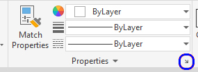
- [STEP 02] Or press [Ctrl+1] on your keyboard to open the Properties panel
- [STEP 03] Place the panel on your left side of the workspace
- [STEP 04] Click [Layer Properties] on Home Ribbon to open Layer properties
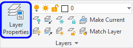
- [STEP 05] Place the panel on your left side of the workspace and click the arrow to hide the panel

The interface after setting changes
(CO5) Types and structure of drawings in Auto CAD- Floor plan, RCP, Elevation, Section, & Details
Architects and Designers use AutoCAD in slightly different ways. It is different from firm to firm and depending on who draws the drawing. Moreover, it depends on what phase of the design you are in.
Many design firms never use layout tabs. Some firms use AutoCAD only for Schematic Design purposes. Some designers use this application for presentation purposes too.
However, in this course, we are targeting to use all essential functions to generate a Construction Document set.
Below is a typical – fundamental – Construction Document set for an interior design project
- Cover sheet + general project information
- Floor plans
- Furniture + Finish plans
- Ceiling plans
- Elevations + Sections
- Details
For detailed information about the types of drawings, please refer
Kilmer, W. Otie, and Kilmer, Rosemary. Construction Drawings and Details / W. Otie Kilmer and Rosemary Kilmer. Third ed. 2016. Print.
(CO6) Input commands and understand different selections
To draw in AutoCAD, you must understand different types of command input
- Use icons on Ribbon (Basic level)
e.g. Click [Home] ribbon > Click [Text] - Use the commands box (Moderate level)
e.g. Click [command box] > Type MULTILINETEXT > Enter key - Use Shortcuts (Advanced level) – Please practice to improve the speed of work and productivity.
e.g., Type [MT] on a keyboard (mouse can be located anywhere, it can be lower case) > Enter
Often use shortcuts by the instructor [please remember the list of shortcuts]
- [l] – line
- [pl] – polyline
- [mt] – multiline text
- [m] – move
- [co] – copy
- [ro] – rotate
- [z] – zoom and [a] – all
- [b] – block
- [s] – stretch
- [x] – explode
- [ex] – extend
- [c] – circle
- [re] – regen (refresh)
- [h] – hatch
- [o] – offset
- F3 – osnap
- F8 – ortho
Detailed information can be found in this link https://www.autodesk.com/shortcuts/autocad
Three types of selections
one click – individual objects
- window selection (blue) – drag/click from left-top to right bottom to select all objects that are enclosed in the selection rectangle.
- cross selection (green) – drag/click from right bottom to left to select all objects crossed by the selection rectangle.
Tip. To select multiple objects, just click one and another. No need to hold [shift] key or [ctrl]
Refer to this link for select object Information from this link
(CO7) Understand essential drawing tools- Origin and Rectangle
Understand the “origin” of the drawing
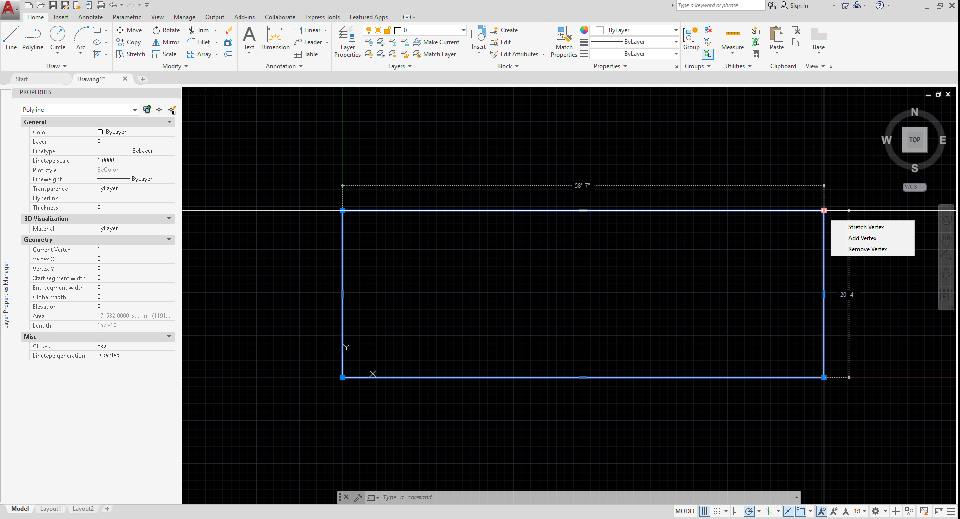
AutoCAD drawing area is on a real scale, which means the drawing scale is 1:1 scale. Moreover, the drawing area is unlimited. You can draw the entire earth in the drawing. Furthermore, you can draw a small object, too. Designers often lose the point/location that they want to draw in the drawing when you draw in a big drawing. Thus, designers use the drawing origin (0,0,0) – ((x,y,z) for a 3D model) as the base point of the project. Usually, the origin of the drawing is the left-bottom corner on the first floor (if it is a 3D model). In AutoCAD, we use only (0,0) – (x,y).
To start your drawing, draw a building footprint or property line first.
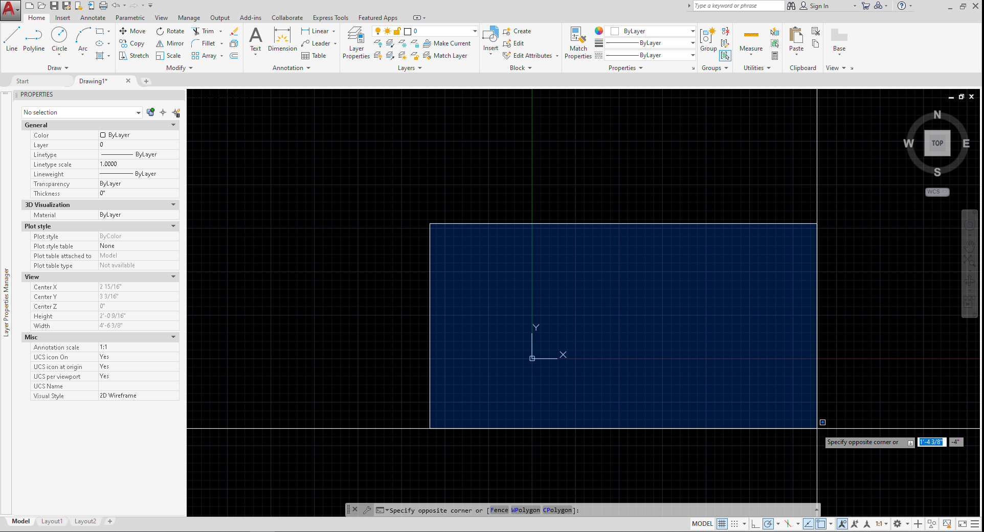
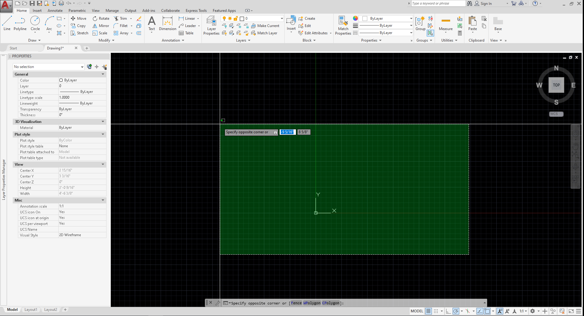
- [STEP 1] Click [Rectangle] on the Home Ribbon, or type [rec] and Enter
- [STEP 2] Specify the first point, type [0,0] and Enter
- [STEP 3] Specify the next point. Any point on the right-top corner will be fine. It depends on the project size. For our project, type [58’7″,20’4″]
- [STEP 4] Type [z] to zoom and type [a] and Enter
Line (command)
- [STEP 1] type [l] and Enter
- [STEP 2] specify the first point by clicking a point or typing [x,y]
- [STEP 3] specify the end point by clicking a point or typing [x,y] – absolute point, type [@x,y] – relative point
- Please refer to this link for the line command
Move (command)
- [STEP 1] type [m] and Enter
- [STEP 2] select the object/objects that you want to move and Enter
- [STEP 3] specify the base point
- [STEP 4] specify the second point to move the object/objects
- Please refer to this link for the move command
Copy (command)
- [STEP 1] type [co] and Enter
- [STEP 2] select the object/objects that you want to copy and Enter
- [STEP 3] specify the base point
- [STEP 4] specify the second point to copy the object/objects
- [STEP 5] specify the third point or more to copy the object/objects if you have. If you want to stop, use ESC
- Please refer to this link for the copy command
- Please practice Line, Move, Copy, and Rotate commands
(CO8) Attach image/PDF/CAD and adjust the scale of the attached file
Download a floor plan image (Eames House-House)
From this page, click [Eames_House_Floor_Plan_House.jpg] and mouse right-click to save the image file to your project folder.
Your CAD file and JPG file MUST be in the same folder. Otherwise, you have to relink the file every time or set your link relatively.
Insert the image file.
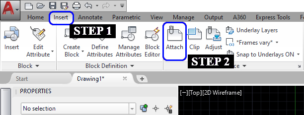
- [STEP 1] Click [Insert] on the ribbon tab
- [STEP 2] Click [Attach] on the Reference palette
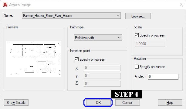
- [STEP 3] Select [Eames_House_Floor_Plan_House.jpg] from your project folder > Click [open]
- [STEP 4] Click [OK] on the Attach Image window
- [STEP 5] Click the origin point or type [0,0] and Enter
Adjust scale
- [STEP 1] Specify the scale factor [1] and Enter
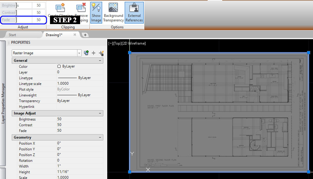
- [STEP 2] Select the inserted image > Change the Fade value to [50] or lower that you can see the background
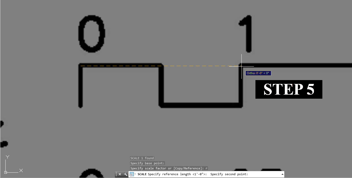
- [STEP 3] Zoom in to the scale or a known dimension
- [STEP 4] Type [SC] and Enter for Scale change
- [STEP 5] Click a base point > Type [r] and Enter > Click the base point > Click a second point that you know a dimension (for this draw, you can use the scale bar) > Type the known dimension [1′]
Change the drawing order
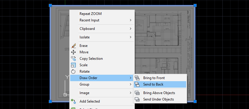
- [STEP 1] Click the inserted image
- [STEP 2] Mouse right-click > Click [Draw Order] > Click [Send to Back]
Move the image to the building footprint
- [STEP 1] Select the inserted image
- [STEP 2] Type [m] to move and Enter
- [STEP 3] Click a base point > Click the target point to move
- Tip! Use Object snap [F3] to select the target point from the building footprint.
(CO9) Set the project folder, Save the file, and backups
Save the file
It is vital to save your file as early as possible. Moreover, save anytime, and the moment you think it is appropriate. I usually save within 15 min (at least four times per hour).
- [STEP 01] Click [Application menu] > Click [Save]
- [STEP 02] Select a project folder on your hard drive, external hard drive, USB, Dropbox, or Onedrive
- [STEP 03] Recommended file type – AutoCAD 2007/LT2007 Drawing(*.dwg)
- [STEP 04] Recommended file name – Eames_House_Project_Firstname_Lastname_01.dwg
Tip! (.bak) file is a backup file. In the default setting, every 10 minutes, the file will be saved. To use the backup file, change the file extension (.bak) to (.dwg)
 References
Narayan, K. Lalit (2008). Computer Aided Design and Manufacturing. New Delhi: Prentice Hall of India. ISBN 978-8120333420.
Pottmann, H.; Brell-Cokcan, S. and Wallner, J. (2007) “Discrete surfaces for architectural design” Archived 2009-08-12 at the Wayback Machine, pp. 213–234 in Curve and Surface Design, Patrick
Chenin, Tom Lyche and Larry L. Schumaker (eds.), Nashboro Press, ISBN 978-0-9728482-7-5.
“Chapter 8 : Autodesk and AutoCAD” (PDF). Cadhistory.net. Retrieved 2020-07-11. http://cadhistory.net/08%20Autodesk%20and%20AutoCAD.pdf
