
Part One. AutoCAD
Chapter 6. Set sheets
- (CO 1) Understand Model space and Paper space
- (CO 2) Set a new layout – Page layout and plot styles
- (CO 3) Set views in Paper space – Defpoints, scaling
- (CO 4) Add/Edit/Draw a titleblock
 Session Highlights
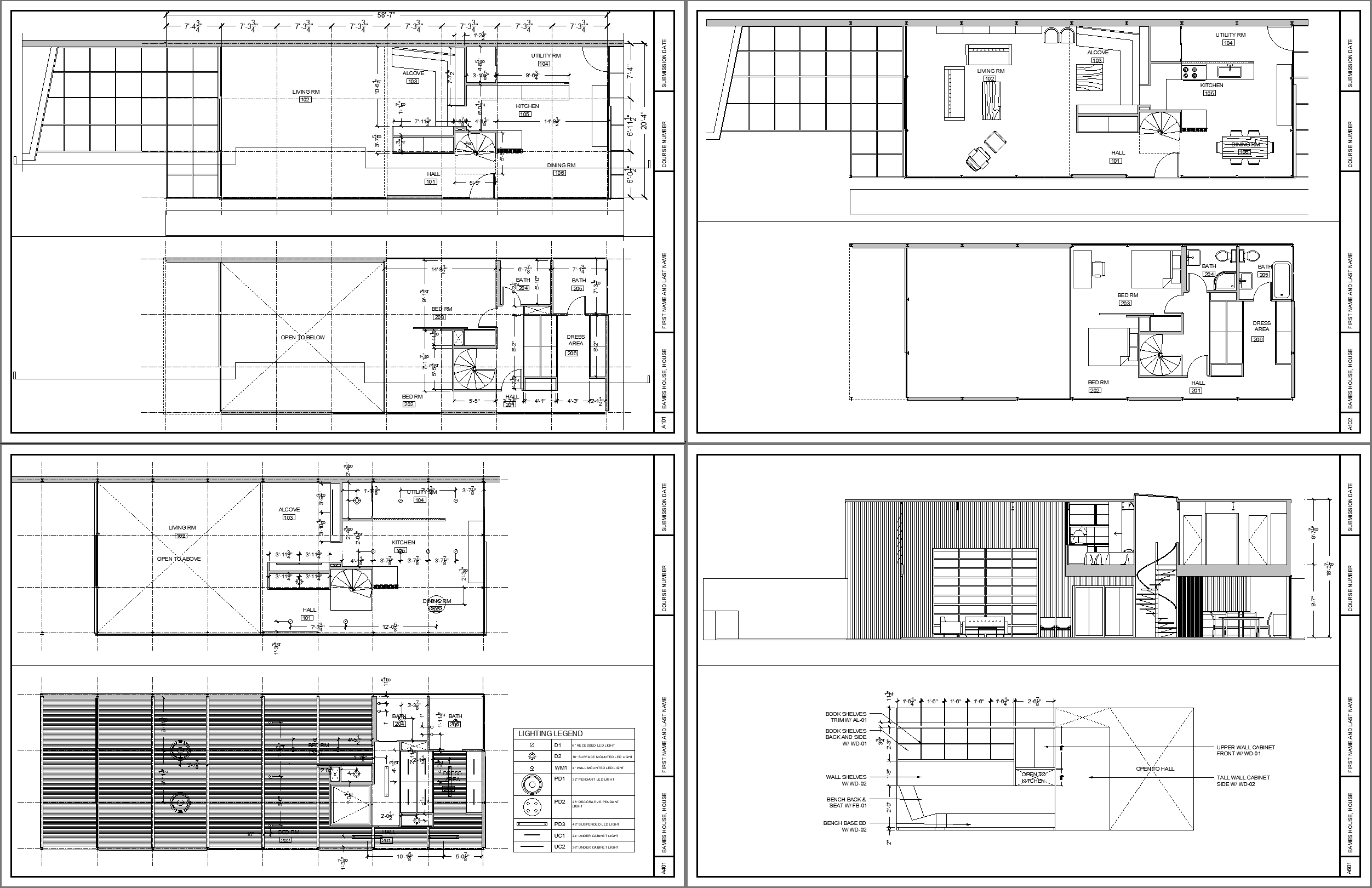
At the end of the session, students can create the graphics below.
 Lecture Contents
(CO 1) Understand Model space and Paper space
In this tutorial, you will understand the differences between the concept of model space and the concept of paper space. AutoCAD provides two different types of drawing areas.
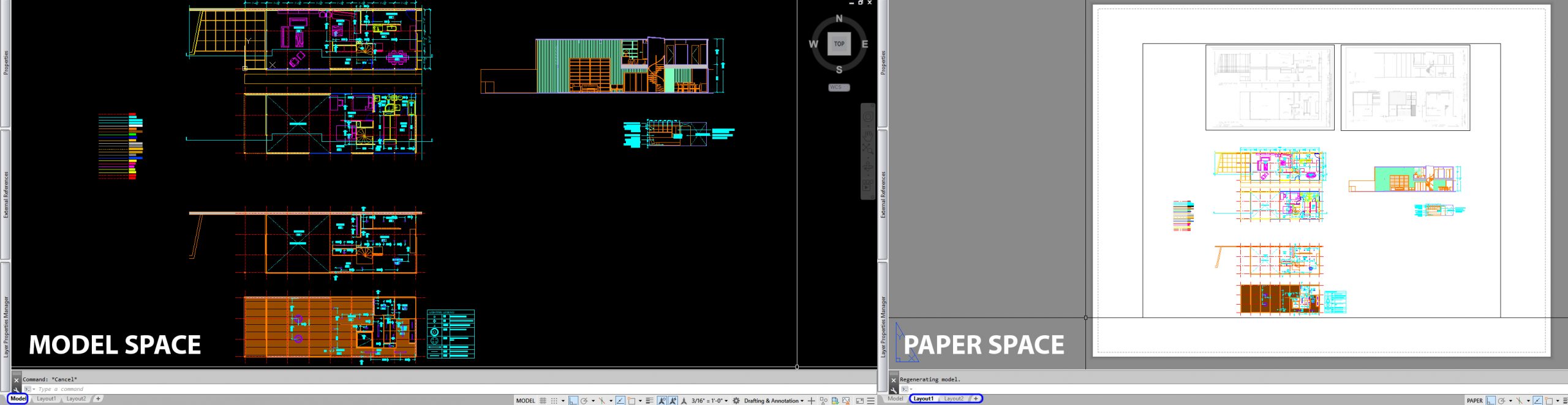
- Model space – A limitless drawing area. You draw at a 1:1 scale.
- Paper space – To prepare your drawing for printing, use paper space. Paper space is a pre-defined and set area. Please refer to the information from this link.
Clean up the CAD file
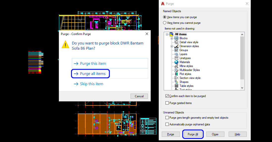
- Purge is a command to automatically removed all layers, blocks, dimension styles, and more items that are not currently used in your document. This command is a useful command to reduce the file size.
- Type [PURGE], and press [ENTER] key, select [PURGE ALL], and purge all again until the [PURGE ALL] is grayed out.
(CO 2) Set a new layout – Page setup
In this tutorial, you will understand how to set a new layout in the paper space using page setup.
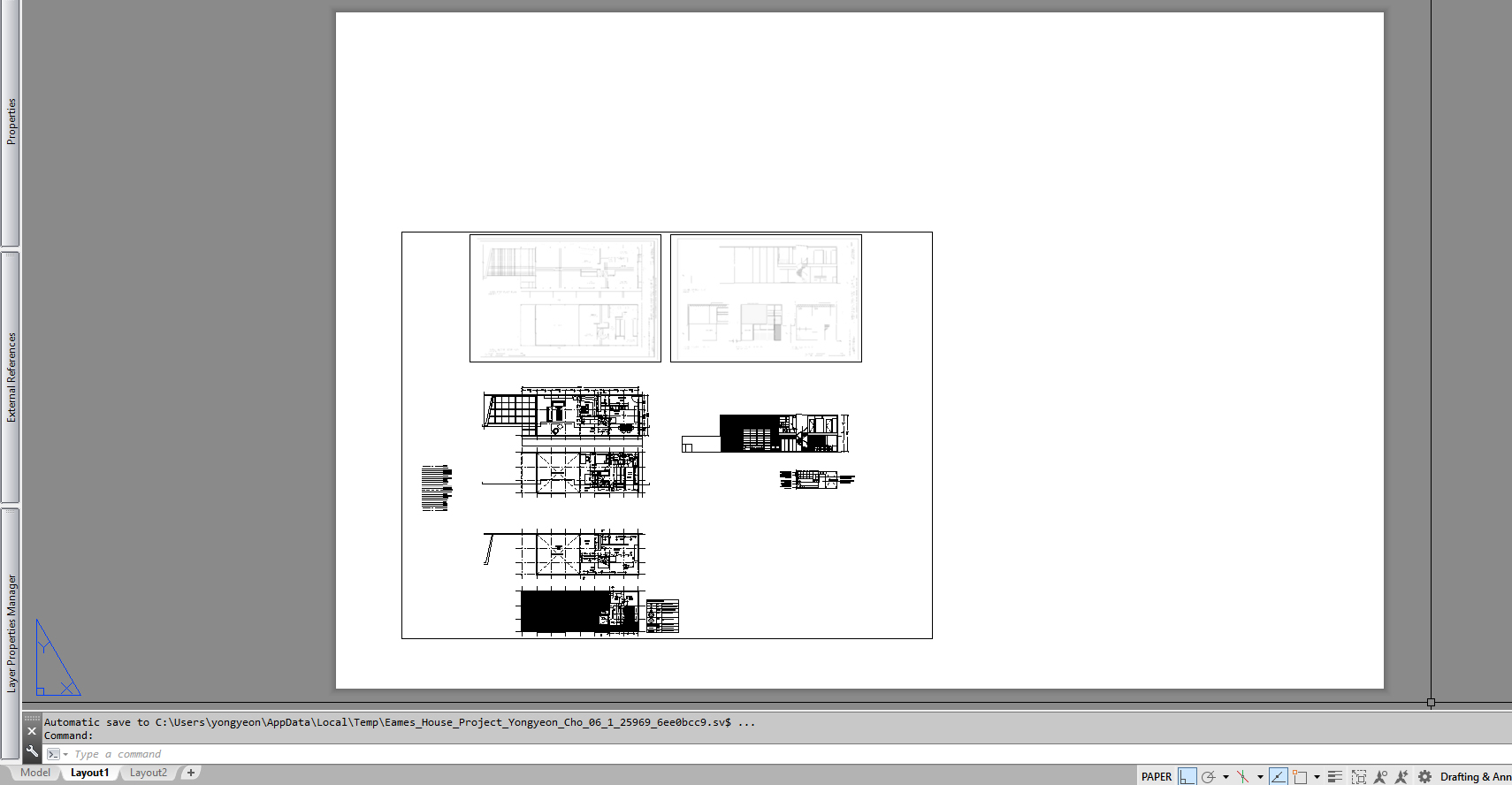
Once you click [LAYOUT 1], you will see the models you made in the model space in a rectangular box. It is called a viewport.
There is a dashed line that is inside of the white space; it is called a printable area.
And the white space called a layout. Once you change the paper size to print, the layout and the printable area will change accordingly.
Update Page setup for 11in x 17 in PDF
- [STEP 1] Open Page setup manager
- Mouse right-click on [LAYOUT 1]
- Click [PAGE SETUP MANAGER]
- Click [*Layout1*] and select [MODIFY] to open the Page setup
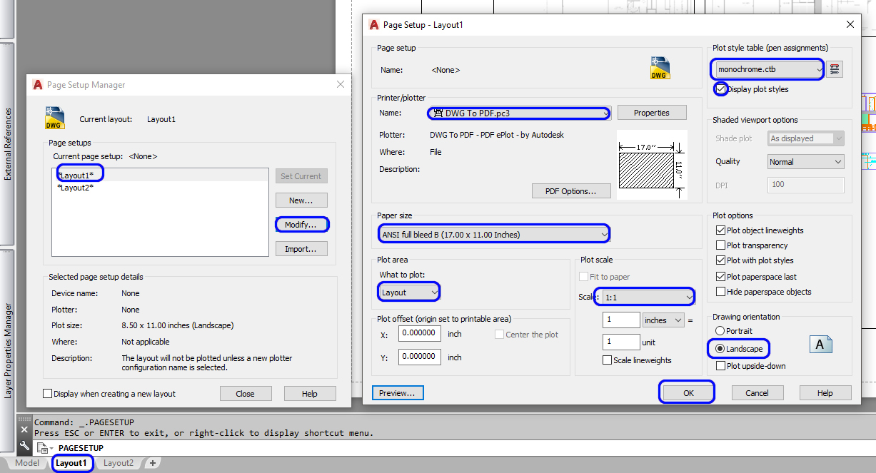
- [STEP 2] Edit Page Setup
- Click the name of printer/plotter and switch to [DWG To PDF.pc3]
- Update paper size to [ANSI full-bleed B (17.00 x 11.00 Inches)
- Confirm What to plot: [LAYOUT]
- Confirm Plot scale to [1:1]
- Change Plot style table to [monochrome.ctb]
- Check [Display plot styles]
- Check [Landscape] for the drawing orientation
- Click [OK] – Page Setup – Layout 1
- Click [Close] – Page Setup Manager
- [STEP 3] Confirm the layout with an updated sheet size
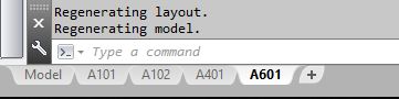
- [STEP 4] Update the name of the sheets and add sheets
- To update the name of sheet > mouse-right click on the tab > Click [RENAME] > Rename on the tab
- To add a sheet > click [+] tab
- Update the name of Layout1 to A101. A101 is for the floor plans
- Update the name of Layout2 to A102. A102 is for the furniture plans
- Add a new layout and change the name to A401. A401 is for RCPs
- Add a new layout and change the name to A601. A601 is for the section view and the elevation
- [STEP 5] Update other sheets to 11×17 PDF
- Mouse right-click on A102
- Open Page Setup Manger
- Select *A101*
- Click [Set Current]
- Click [Close]
- Repeat this process for A401 and A601
(CO 3) Add/Edit/Draw a titleblock
- [STEP 1] Draw a titleblock
- Select [A101] sheet to open the sheet
- Confirm your current layer is [0]
- Draw a rectangle for a paper size box – Type [REC], press [Enter] key > Type [0,0], press [Enter] key > Type [17”,11”]. Press [Enter] key
- Draw a titleblock outline using the paper size box – Type [O], press [Enter] key > Type [1/4”], press [Enter] key > Click the inside of the sheet
- Draw lines for the titleblock. Please refer to the image below
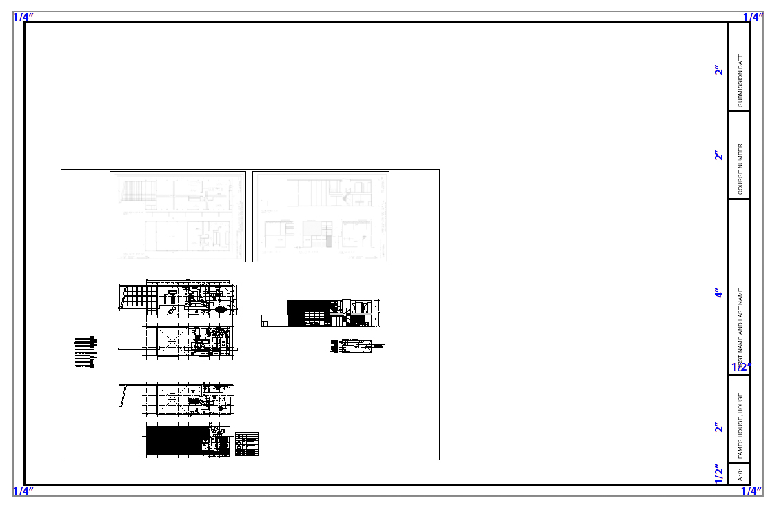
- [STEP 2] Add titleblock information
- Sheet number – A101
- Project name – Eames House, House
- Your name – First name and last name
- Course number
- Submission date
- Add text using [MT] for titleblock information. Verify the text size is 3/32”. You may rotate the text 90 degrees.
- [STEP 3] Add the titleblock to other sheets
- Click [Inset] from [Insert] tab, on [Block] panel
- Select [000_Titleblock_11x17]
- Type [0,0], press [Enter] key
- Select the titleblock and the information except for the Sheet number.
- Create a block for the selected elements – Name the block – [000_Titleblock_11x17]
- Insert the titleblock to A102, A401, and A601
- Switch the Titleblocks to [A-ANNO-TTLB]
- Copy and modify the sheet number to A102, A401, and A601
- Now you are ready to add a titleblock on the paper space.
(CO 4) Set views in Paper space – Defpoints, scaling
Now you are ready to set the views in the sheets
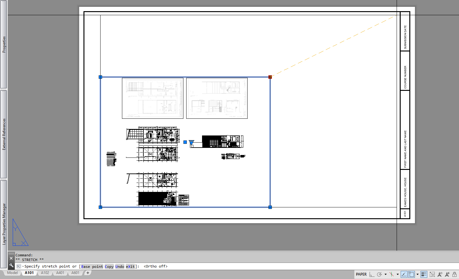
- [STEP 1] Change a viewport size and the viewport layer
- Once you click, a viewport can be changed by stretching the corner of the viewport line.
- Once you click, a viewport can be changed by stretching the corner of the viewport line.
-
- Select the viewport > switch to [Defpoints] layer. The [Defpoints] layer is set up by default as a non-plot layer.

- Select the viewport > switch to [Defpoints] layer. The [Defpoints] layer is set up by default as a non-plot layer.
- [STEP 2] Update the scale of the viewport
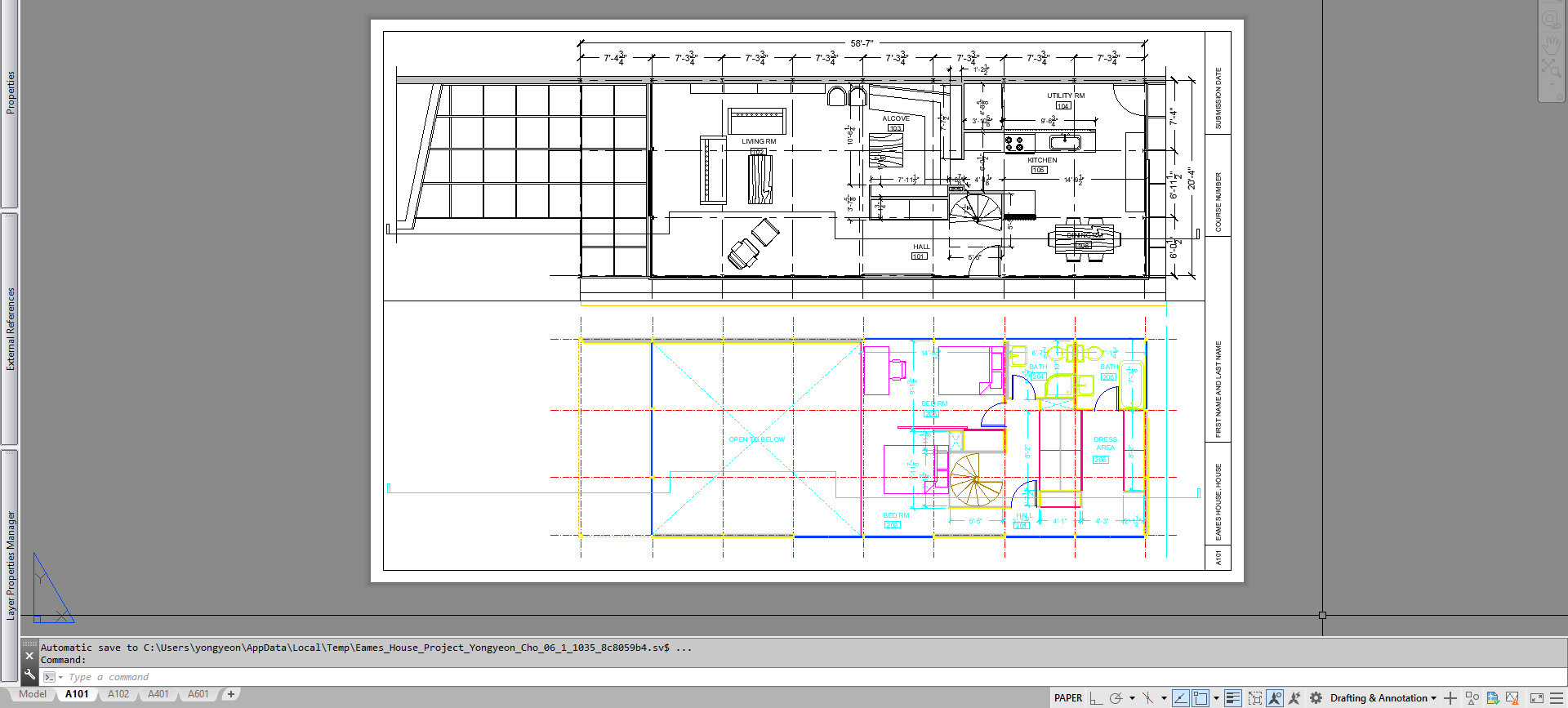
- After changing the viewport size > double-click the viewport > Zoom in and out > Pan the view to make the view centered
- After changing the viewport size > double-click the viewport > Zoom in and out > Pan the view to make the view centered
-
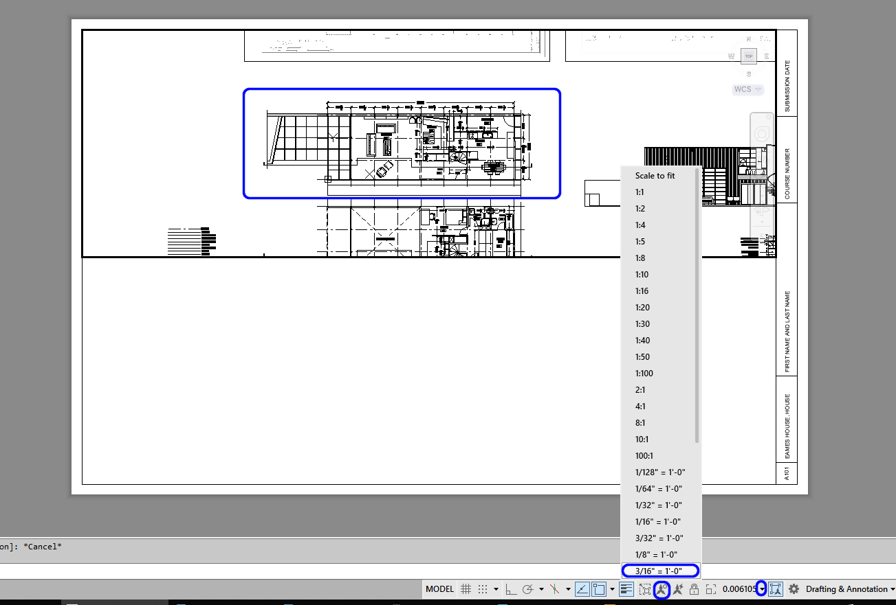
- Click a scale on the application status bar, and select a desired scale for the floor plan
- If the dimensions have disappeared, click on the Show Annotation icon on the application status bar
- [STEP 3] If you want to add a new viewport, use the [MVIEW] command.
- Type [MV], and press [Enter] > Click the first point to draw a rectangle > Click a second point to finish the rectangle. It will automatically show the drawings
- If you have a viewport to copy, you can copy the viewport and pan the view
- Sometimes a copied viewport will show in color. To change it to black and white, double-click the inside of the viewport > type [RE] and press [ENTER] key > double-click the outside of the viewport
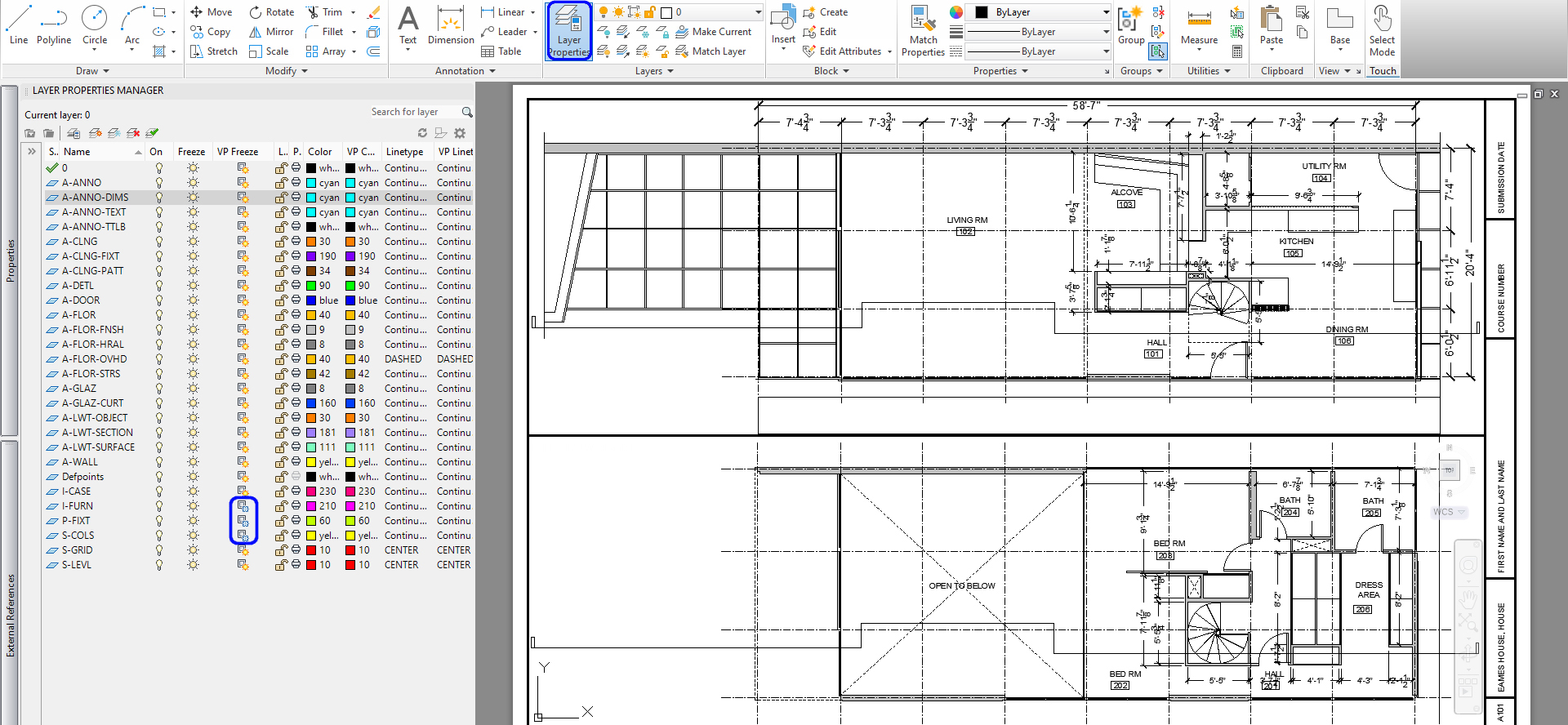
- [STEP 4] Update layer visibility for the viewports
- Open [LAYER PROPERTIES MANAGER]
- A101 is for dimensioned floor plans. Thus, it would help if you hid the [I-FURN], [I-CASE], and [P-FIXT] layers
- Double-click the viewport, and click [VP FREEZE] on the I-FURN], [I-CASE], and [P-FIXT] layers
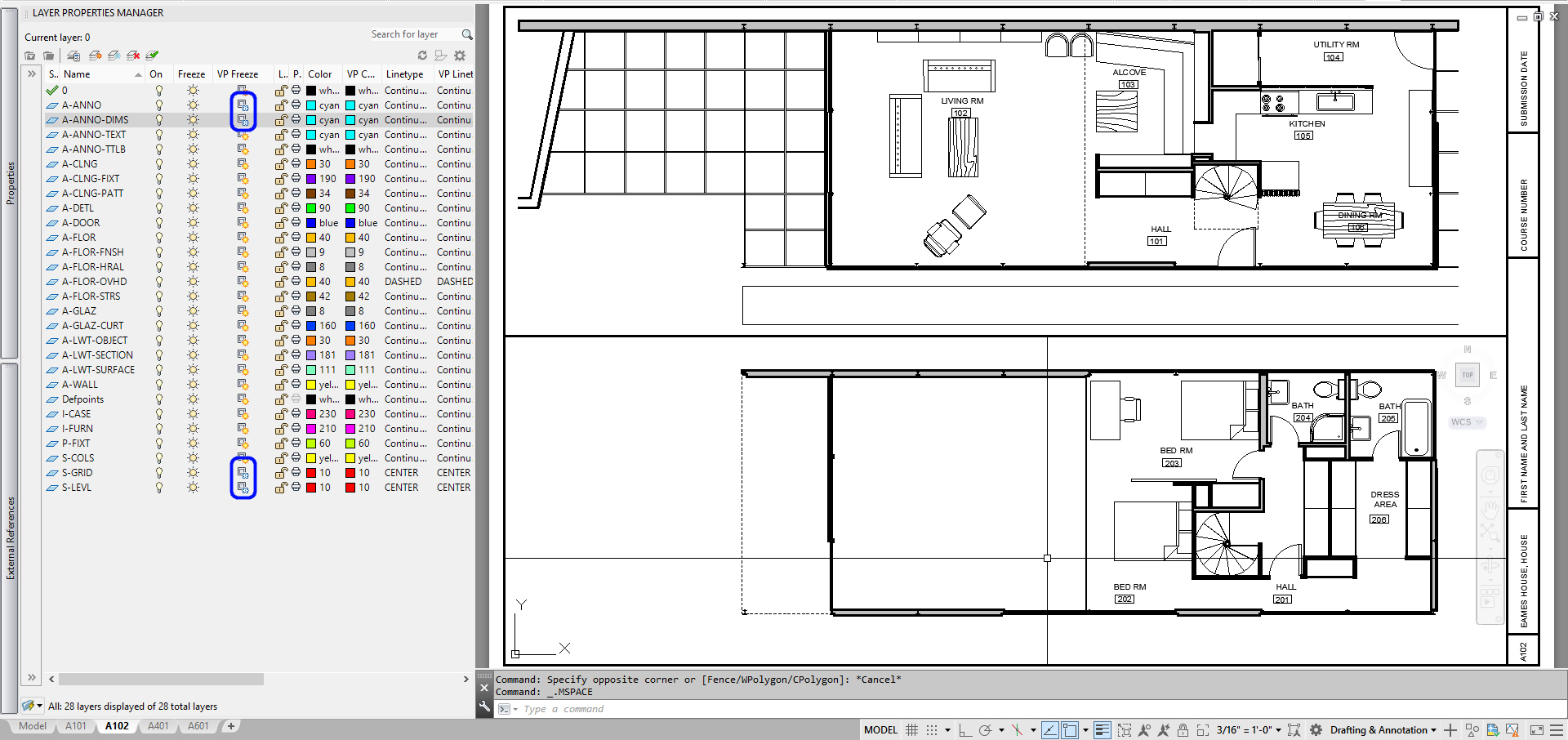
- [STEP 5] Set a furniture plan sheet
- The scale of the furniture plan is 3/16”= 1.’
- VP Freeze [A-ANNO], [A-ANNO-DIMS], [S-GRID], and [S-LEVEL]
- [STEP 6] Set an RCP sheet
- The scale of the RCP is 3/16”= 1.’
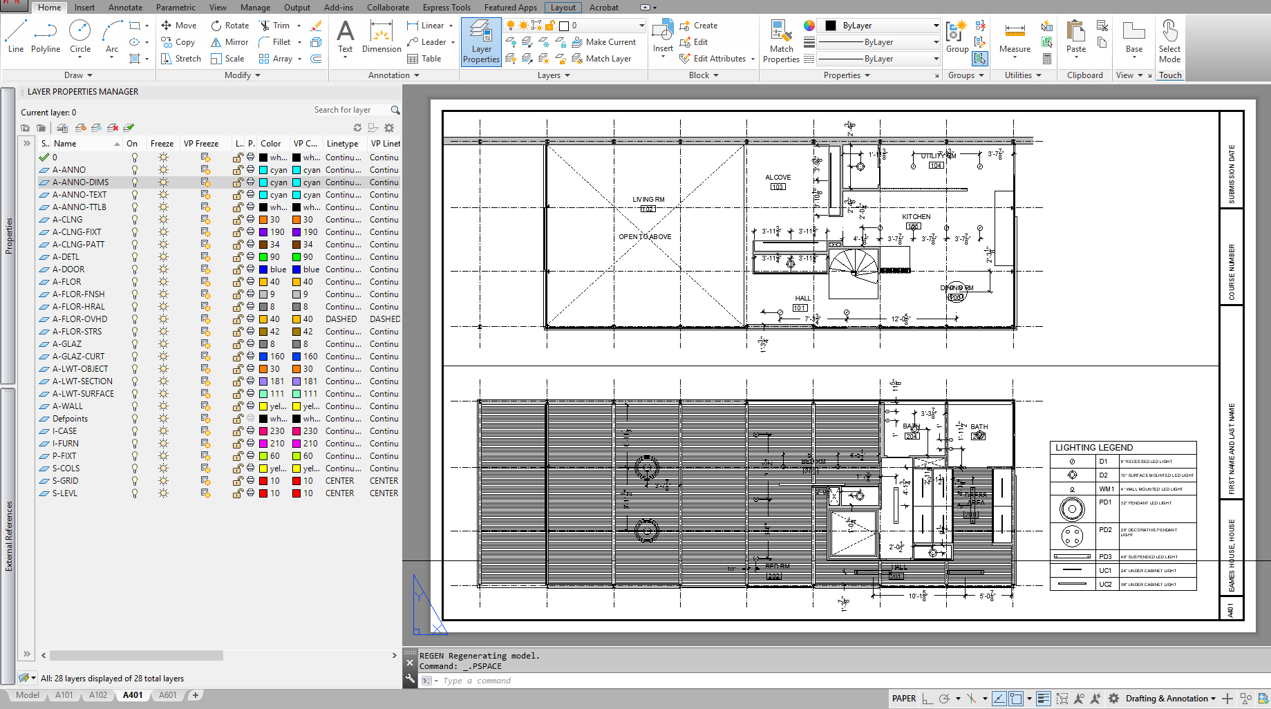
- The scale of the RCP is 3/16”= 1.’
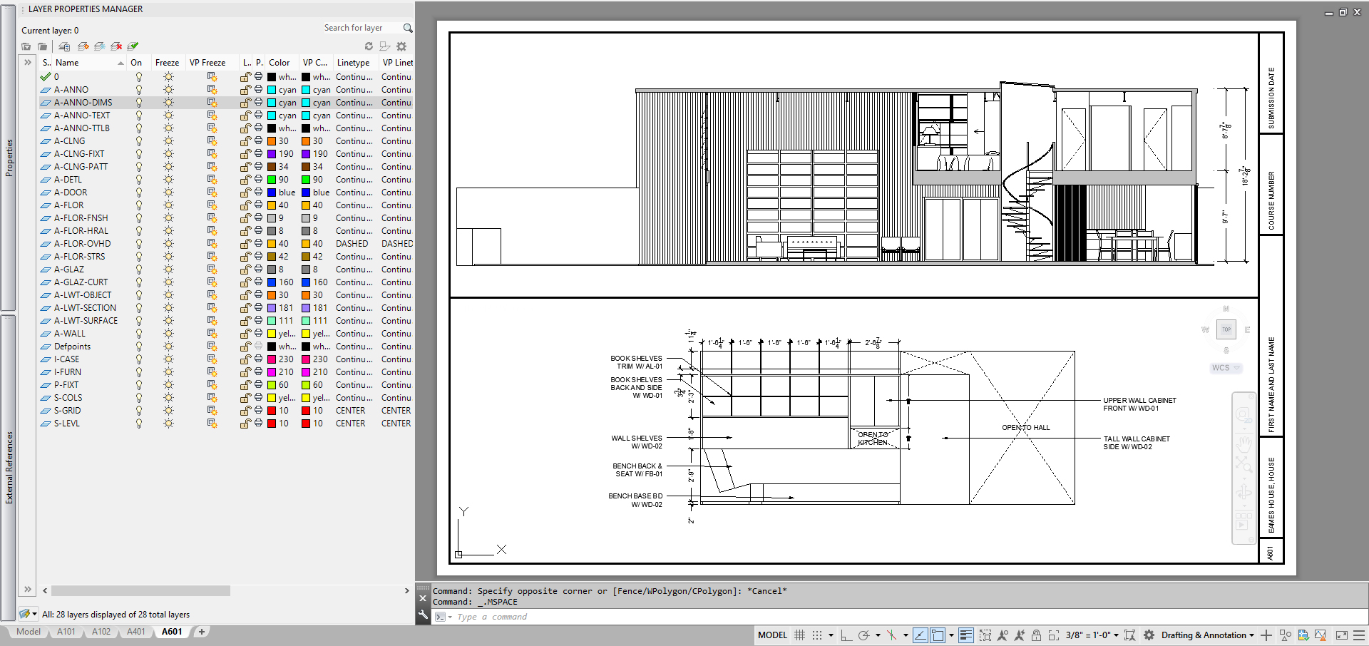
- [STEP 7] Set a section view and elevation sheet
- The scale of the section view is 3/16”= 1.’
- The scale of the elevation is 3/8”= 1.’
SAVE the file before closing the application.
Save in a different location for the backup (e.g., a cloud folder)
 References
Autodesk.Help. (2020, March 29). About Model Space and Paper Space. Retrieved October 20, 2020, from https://knowledge.autodesk.com/support/autocad/getting-started/caas/CloudHelp/cloudhelp/2019/ENU/AutoCAD-Core/files/GUID-990538B6-DDA1-4190-BCC0-BB5BA94C9879-htm.html
