
Part Two. Revit
Chapter 12. Understand visibility settings, add/edit floor & ceilings
Upon completing this session, students will be able to:
- (CO 1) Understand View template, visibility graphics
- (CO 2) Understand View range
- (CO 3) Add/Edit Floors & Floor Properties
- (CO 4) Add/Edit Ceilings & Ceiling Properties
 Session Highlights
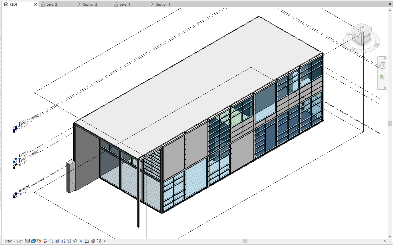
At the end of the session, students can create the graphics below.
 Lecture Contents
(CO 1) Understand View template, visibility graphics
[VIEW TEMPLATE] in Revit is a collection of view properties, such as a scale of a view, detail level, discipline, view ranges, orientations, model display, and visual settings. With using [VIEW TEMPLATE], you can apply standard settings to views.
For example, I can make a Floor plan view template to apply all my floor plans. The floor plans will have the same scale, detail level, and style of lines. And you can also set a Furniture plan template. On the floor plans, you can hide all door tags and window tags at once. View templates save much time when producing a set of construction documents.
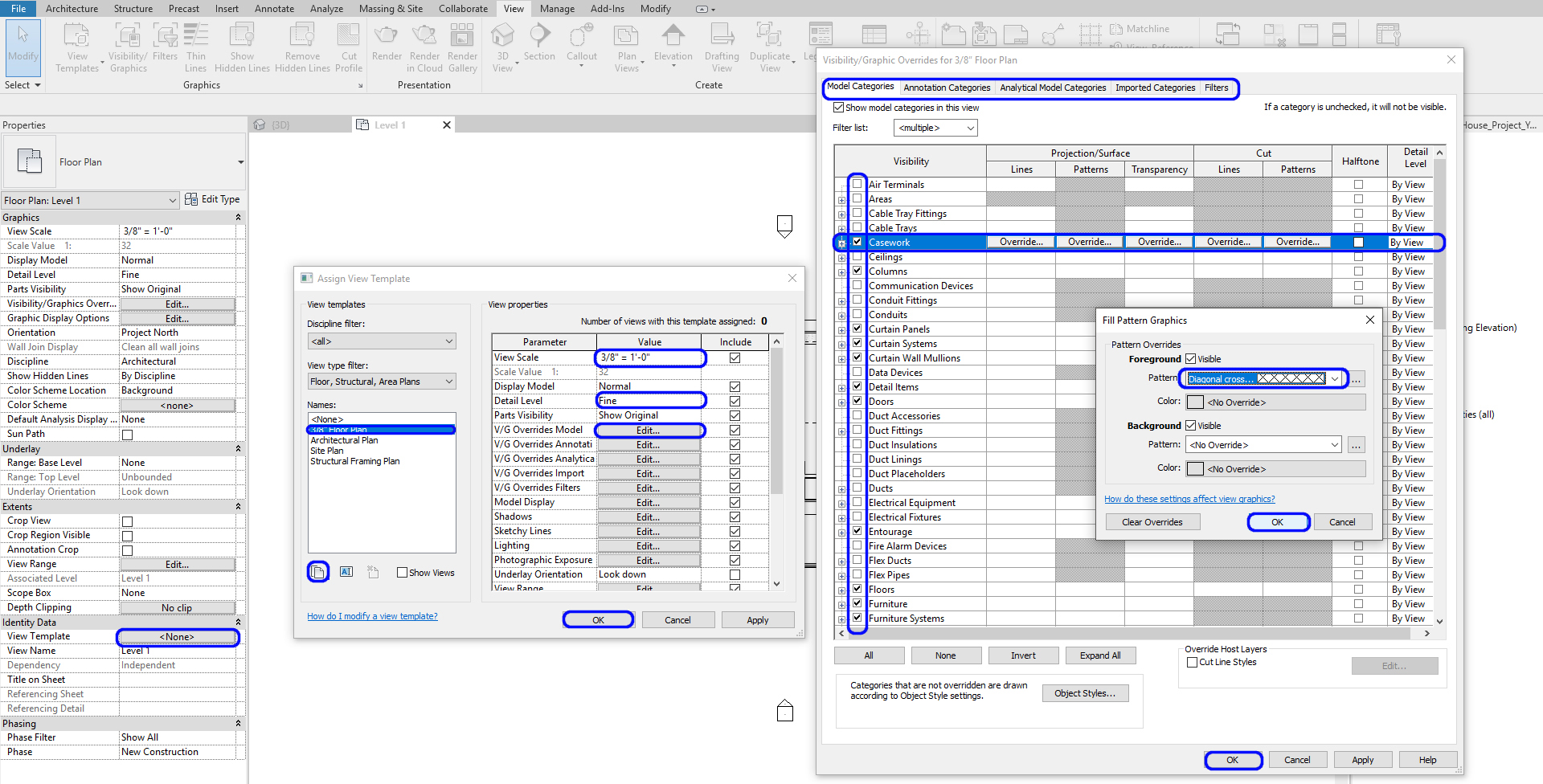
To set a view template
- [STEP 1] Click [VIEW TEMPLATE] from [PROPERTIES] palette, Assign view template window will open
- [STEP 2] Select [ARCHITECTURAL PLAN]
- [STEP 3] Click [DUPLICATE] icon, and Name it [3/8” Floor Plan]
- [STEP 4] Update [VIEW SCALE] to [3/8”=1’-0”]
- [STEP 5] Click [EDIT] on V/G Overrides Model, then Visibility/Graphic Overrides for 3/8” Floor Plan window will open
- [STEP 6] You can hide categories that you don’t want to show in the view by unchecking the categories.
- [STEP 7] Also, you and change the graphic styles by clicking [OVERRIDE]
- [STEP 8] Click [OK]s to apply
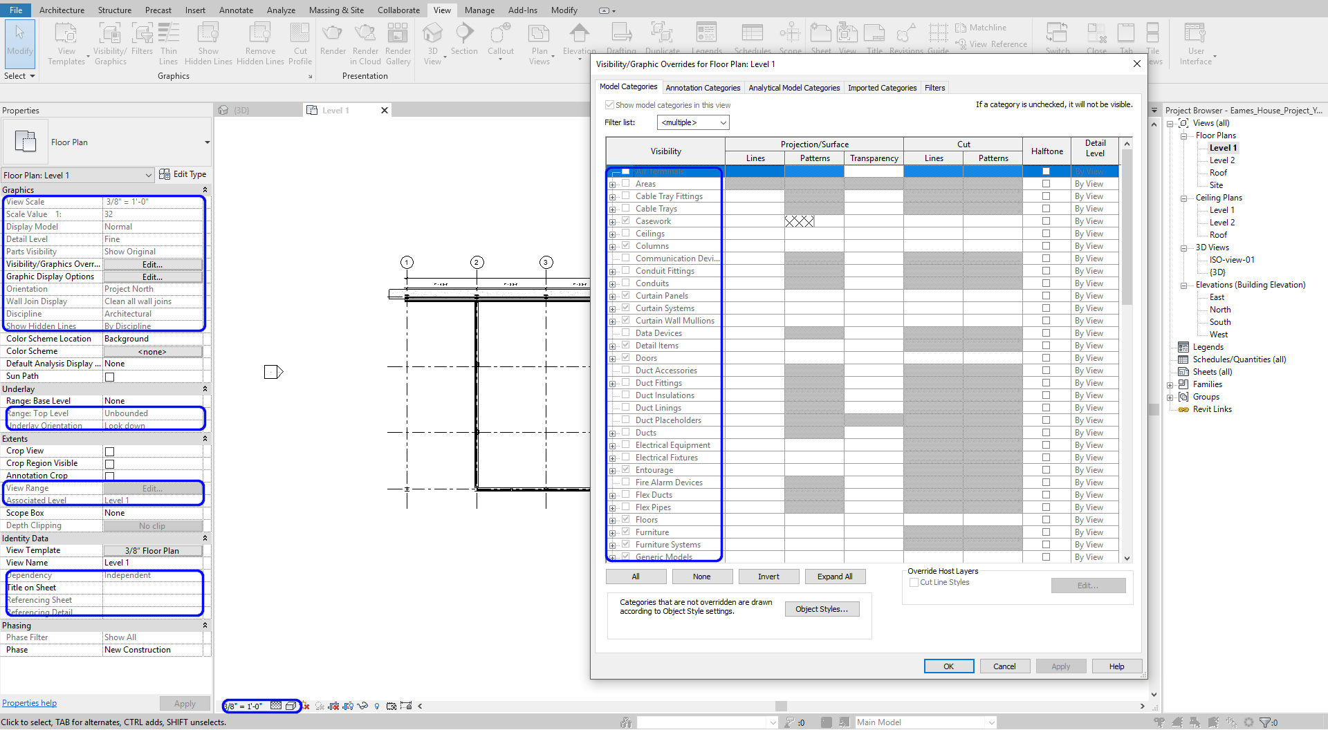
To apply the view template to other views
- [STEP 1] Select a view or multiple views
- [STEP 2] Click [VIEW TEMPLATE] from [PROPERTIES] palette
- [STEP 3] Select the view template you made for the selected views
- [STEP 4] Click [OK] to apply
Once you apply a view template, the visibility/graphic override, view scale, display model, detail level, view range, discipline, phase filter, and more items in the view templates will be deactivated on the view. To change the setting, you have to adjust in the view template, not individually.
If you want to set the view settings individually, you must select [NONE] for the view template.
For more information, please refer to this page for the view template.
(CO 2) Understand View range
[VIEW RANGE] is a set of horizontal planes that control the visibility and display of objects in a plan view.
To adjust view range
- [STEP 1] Click [VIEW RANGE] from [PROPERTIES] palette. If this is deactivated, check your view template and click [VIEW RANGE] from the template.
- [STEP 2] You define the ranges by adjusting the offset value
- [STEP 3] You can see the sample view range for better understanding by clicking [<< SHOW] button
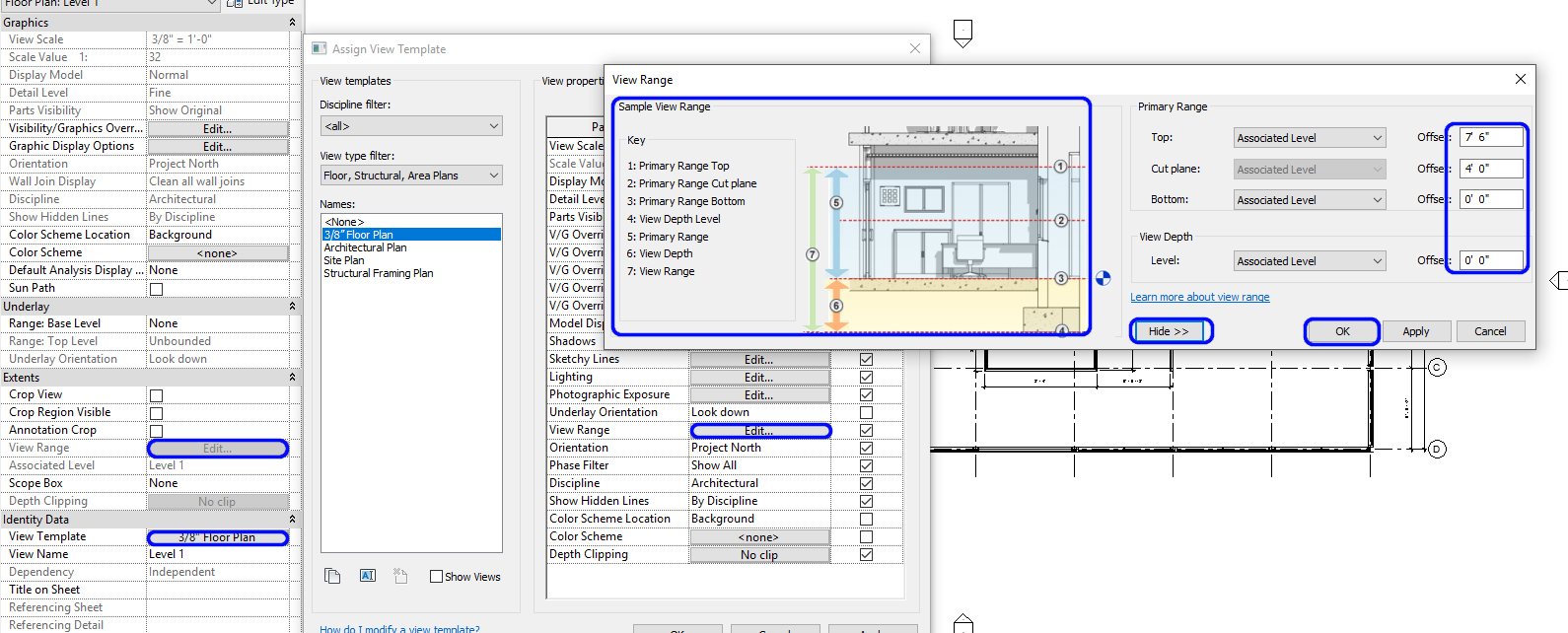
- [STEP 4] Click [OK] to apply
For more information about [VIEW RANGE], please visit this page
[UNDERLAY] is a function to understand the relationship of components at different levels for coordination and construction.
To apply [UNDERLAY]
- [STEP 1] Open the second-floor plan
- [STEP 2] Click Range: Base Level and change the level that you want to look below
- [STEP 3] Click Range: Top Level and change the level that you want to ‘lookup.’
- [STEP 4] For floor plans, the Underlay Orientation should be [LOOK DOWN]
For RCPs, the Underlay Orientation should be [LOOK UP]
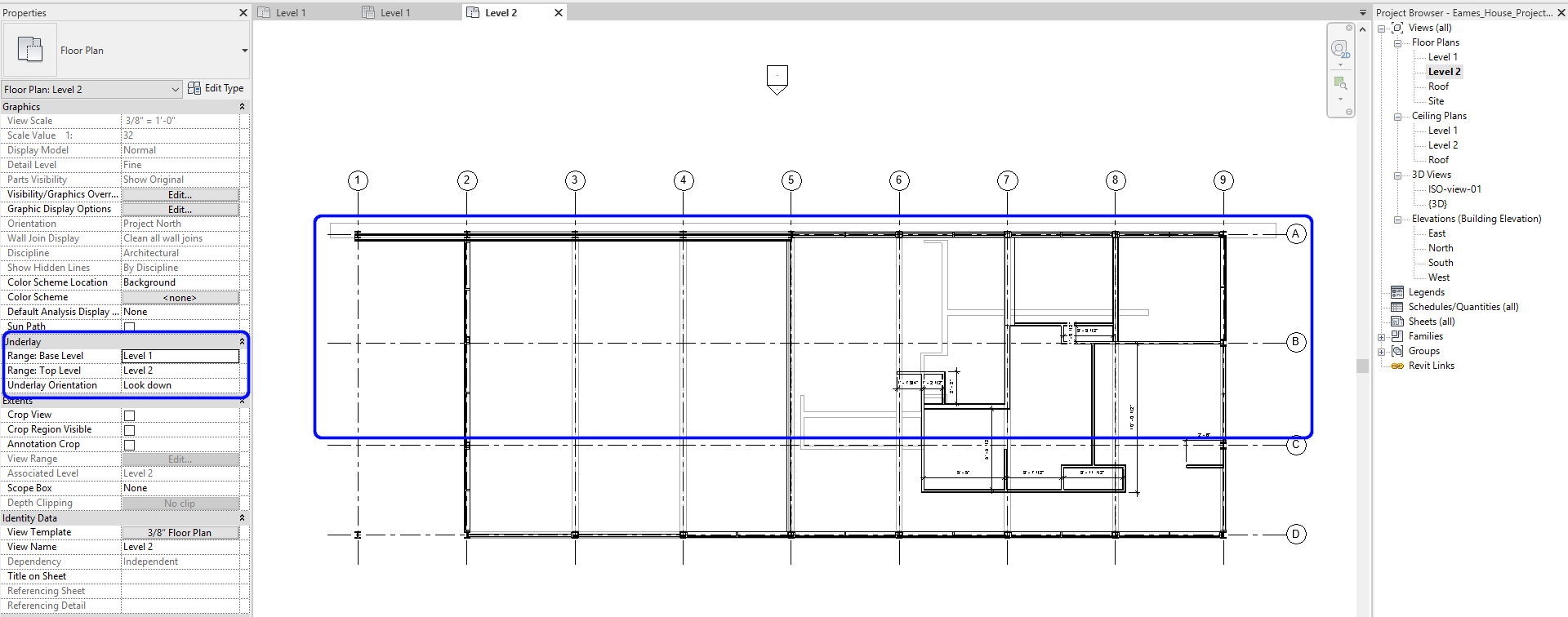
Once the underlay function is activated, you can see the gray lines. You are not able to click nor edit the underlay items.
This function is only for the working process. If you don’t need the underlay items, please check [NONE] on Range: Base Level to deactivate the function.
For more information about [VIEW RANGE], please visit this page.
(CO 3) Add/Edit Floors & Floor Properties
Revit is a BIM software; it needs more information to generate 3D views and Drawings. When in plan view the drawing appears complete much like it does in AutoCAD. However, when you view the Revit model in a 3D view, the floors and ceilings are missing. Therefore, you need to model these elements as well.
There are multiple ways to create floors. I prefer to create a slab(without finishes) and then add finishes over the top of the slab.
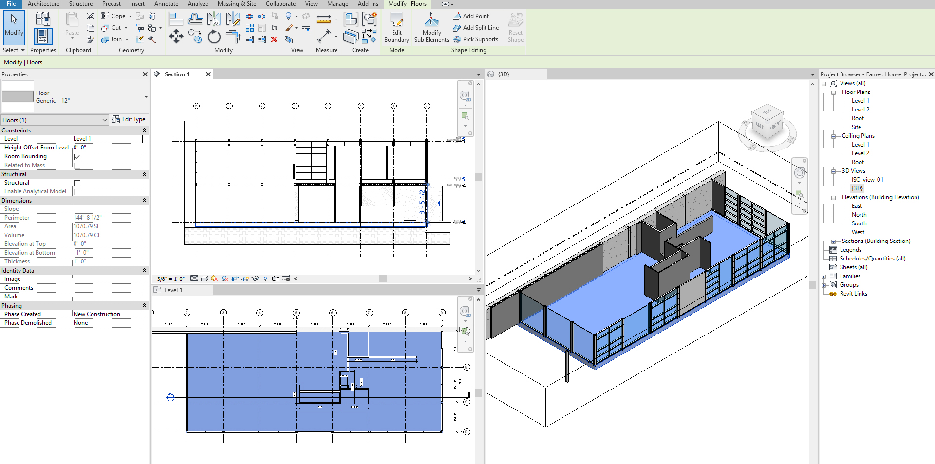
To Add/Edit Floors
- [STEP 1] Select [FLOOR ARCHITECTURAL] from [ARCHITECTURE] tab, under [BUILD] panel
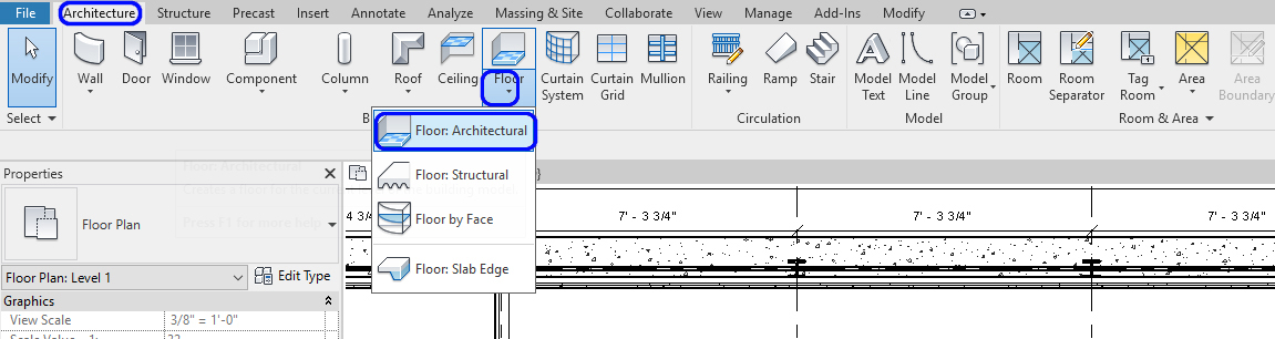
- [STEP 2] Select a Floor Type. For the First Level of Eames House, we will use [Generic – 12”], but we will modify the properties later.
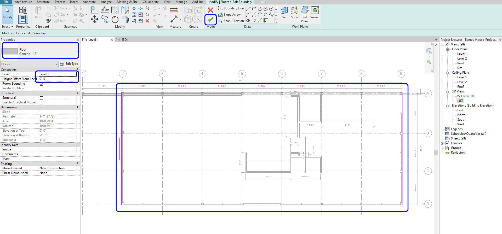
- [STEP 3] Select the level where the floor is located. And specify height offset from the level if required.
- [STEP 4]Draw the boundary of the Floor plan. You can draw using straight lines or any of the other options. Make sure the boundary lines are connected and closed
- [STEP 5] Click the green checkmark to complete the sketch
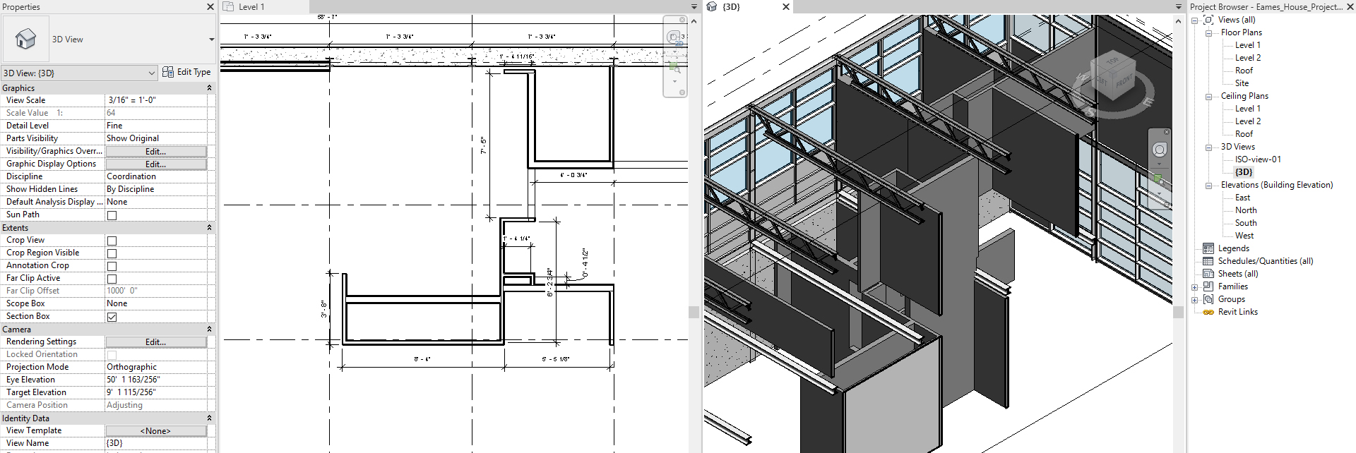
- [STEP 6] Confirm the location on a section view or a 3D view
You can click [SECTION] from the [VIEW] tab, under the [CREATE] panel. And draw a section line for verification purposes.
Make sure your building pod must be below level 1.
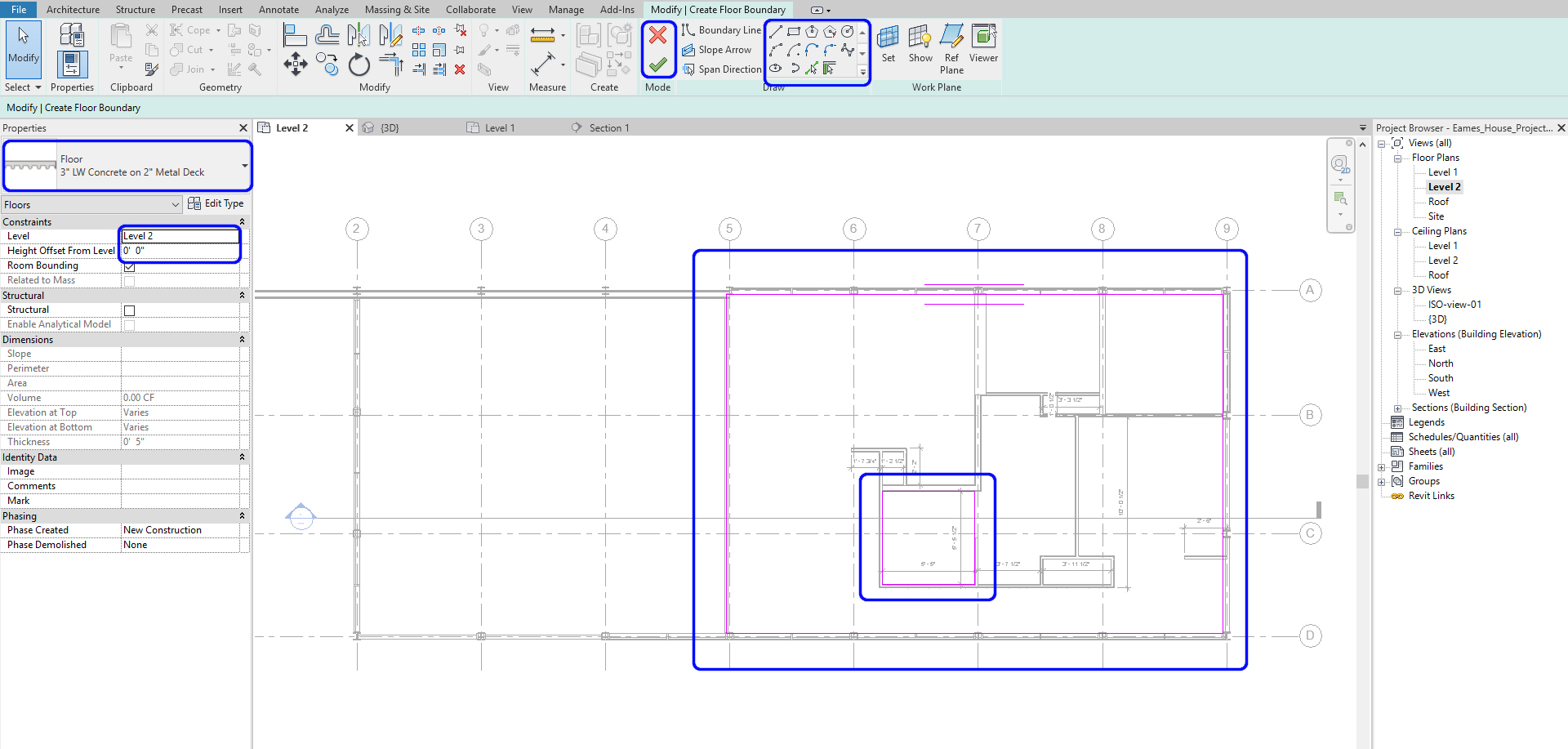
Add a floor for the second level
- [STEP 1] Open [LEVEL 2] floor plan
- [STEP 2] Click [FLOOR] from [ARCHITECTURE] tab, under [BUILD] panel
- [STEP 3] Change the floor type to 3” LW Concrete on 2” Metal Deck, and verify the Level 2, and the Offset
- [STEP 4] Draw continued lines for the floor. If there are floor openings, draw the openings as well. If the openings are inside the boundary of the floor, Revit will recognize as it is opening.
- [STEP 5] Click [GREEN CHECK MARK] to complete the sketches
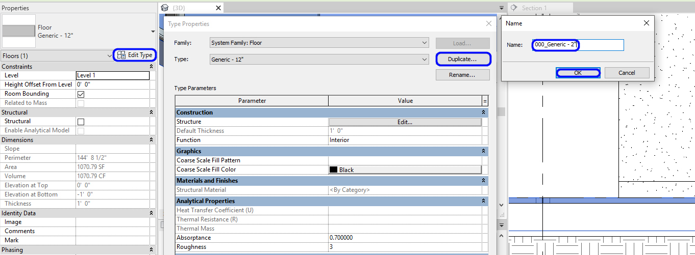
Edit Floor properties
You will change the thickness of the floor 12” to 2.”
- [STEP 1] Select the first level floor from the 3D view
- [STEP 2] Click [EDIT TYPE] on [PROPERTIES] palette
- [STEP 3] Click [DUPLICATE] on [TYPE PROPERTIES]
- [STEP 4] Enter a new name. I recommend adding [000_] of the letter of the name.
For example [000_Generic – 2”] - [STEP 5] then click [OK]
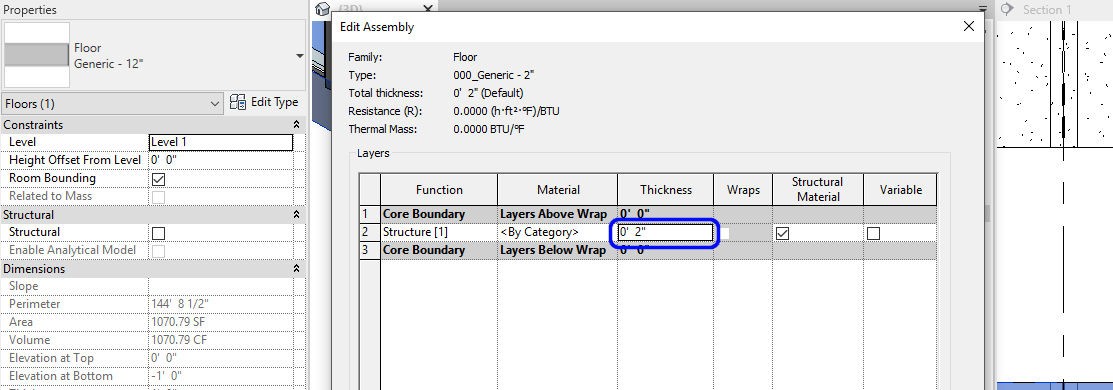
- [STEP 6] Click [EDIT] for [STRUCTURE]
- [STEP 7] Change [2”] and click [OK] and [OK] to complete
Add Floor types
- [STEP 1] Click [FLOOR] from [ARCHITECTURE] tab, under [BUILD] panel
- [STEP 2] Select [Generic – 12”]
- [STEP 3] Click [EDIT TYPE]
- [STEP 4] Click [DUPLICATE]
- [STEP 5] Rename to [000_TL_01], you will need [000_TL_02], and [000_CPT_01]
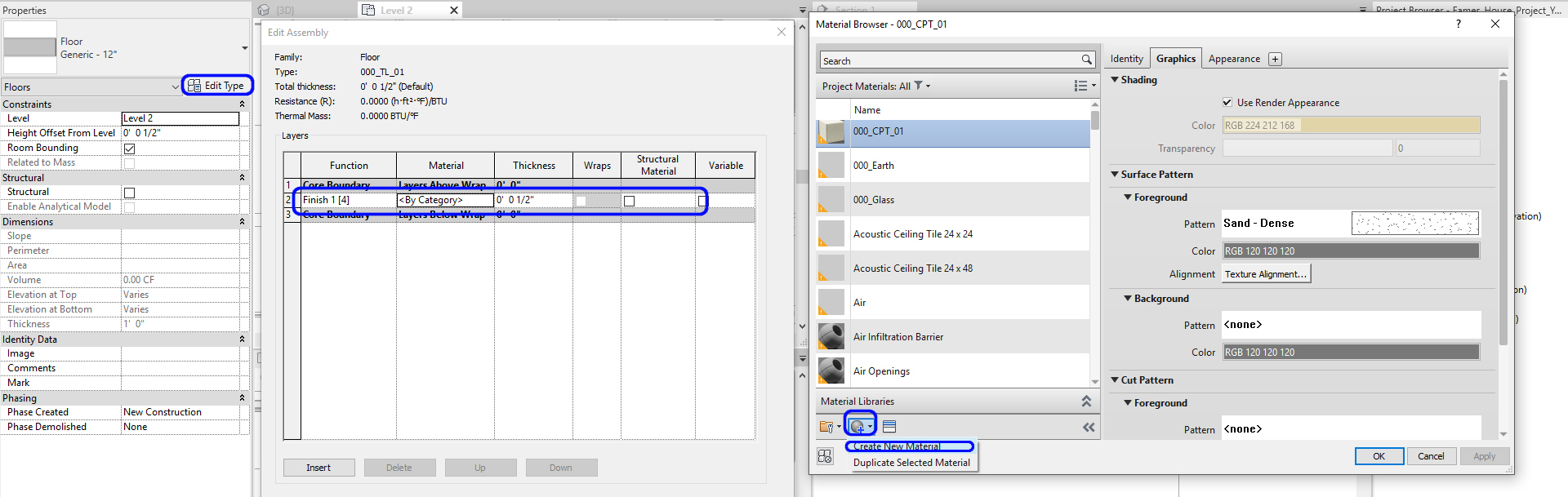
- [STEP 4] Click [EDIT] for [STRUCTURE]
- [STEP 5] Change the Function to [FINISH 1]
- [STEP 6] Change the Thickness to [1/2”]
- [STEP 7] Click <By Category>
- [STEP 8] Click [CREATE A NEW MATERIAL]
- [STEP 9] Rename the new material
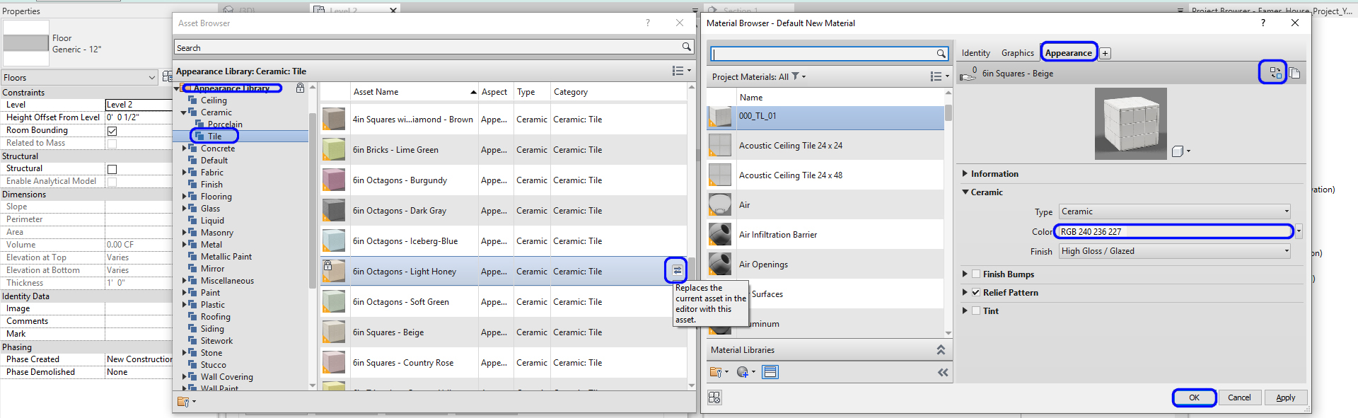
- [STEP 10] Check [USE RENDER APPEARANCE]
- [STEP 11] Change the foreground pattern
- [STEP 12] Click [APPEARANCE] tab
- [STEP 13] Click [REPLACE THIS ASSET]
- [STEP 14] Find appropriate material from [APPEARANCE LIBRARY]
- [STEP 15] Click the [REPLACE] icon, and close the [ASSET BROWSER]
- [STEP 16] If needed, change the color
- [STEP 17] Click [OK]s to complete
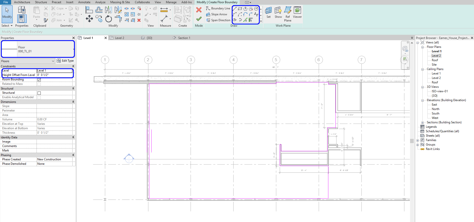
Add floors for finishes
- [STEP 1] Open a plan view to add the finish floor
- [STEP 2] Confirm the level on the [PROPERTIES]
- [STEP 3] Change the Height Offset From Level to [1/2”]
- [STEP 4] Draw Floor Boundary, please consider not to overleap with walls
(CO 4) Add/Edit Ceilings & Ceiling Properties
Add a ceiling
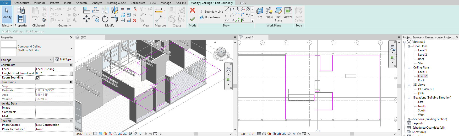
- [STEP 1] Open [LEVEL 1] ceiling plan
- [STEP 2] Click [CEILING] from [ARCHITECTURE] tab, under [BUILD] panel
- [STEP 3] Select [GWB on Mtl. Stud]
- [STEP 4] Confirm [LEVEL] is [LEVEL 1 CEILING] and [HEIGHT OFFSET FROM LEVEL] to [0’0”].
If you don’t have a level for a ceiling, you can set your level to Level 1 and update the height offset from a level like 8’-0.” - [STEP 5] Draw the Ceiling boundary.
You will need to draw an independent ceiling for each room. - [STEP 6] Click the green checkmark to complete this command.
- Repeat this process to place a ceiling at level 2
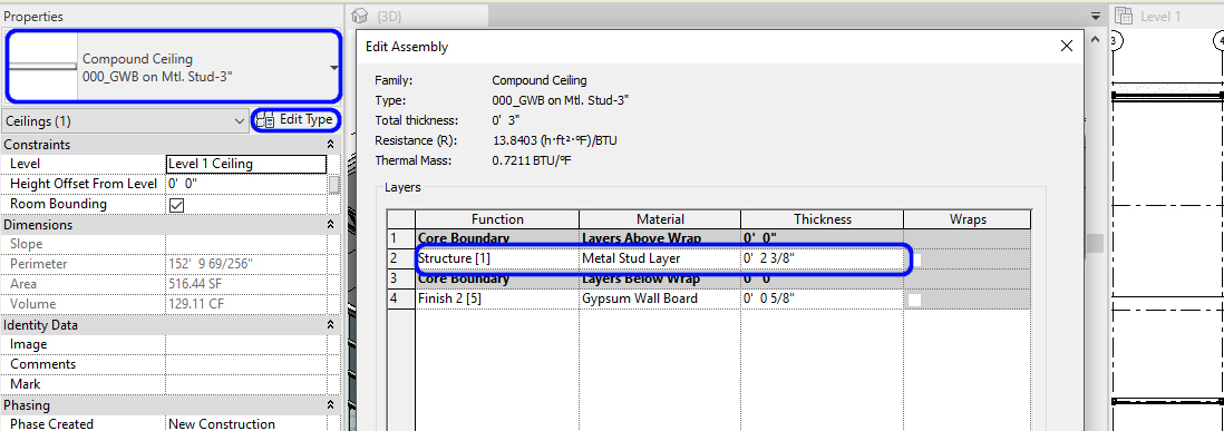
Edit Ceiling properties
You will change the thickness of the ceiling 12” to 2.”
- [STEP 1] Select the first level ceiling from the 3D view
- [STEP 2] Click [EDIT TYPE] on [PROPERTIES] palette
- [STEP 3] Click [DUPLICATE] on [TYPE PROPERTIES]
- [STEP 4] Enter a new name. I recommend adding [000_] of the letter of the name.
For example, [000_GWB on Mtl.Stud-3”] - [STEP 5] then click [OK][STEP 6] Click [EDIT] for [STRUCTURE]
- [STEP 7] Change [2 3/8”] for [METAL STUD LAYER] and click [OK] and [OK] to complete
SAVE the file before closing the application.
Save in a different location for the backup (e.g., a cloud folder)
 References
Autodesk.Help. (2020, May 13). About View Templates. Retrieved October 22, 2020, from https://knowledge.autodesk.com/support/revit-products/learn-explore/caas/CloudHelp/cloudhelp/2018/ENU/Revit-Customize/files/GUID-C3B5FB82-3247-48F6-82F0-73011A0F8027-htm.html#:~:text=A%20view%20template%20is%20a,consistency%20across%20construction%20document%20sets
Autodesk.Help. (2019, February 18). About the View Range. Retrieved October 22, 2020, from https://knowledge.autodesk.com/support/revit-products/learn-explore/caas/CloudHelp/cloudhelp/2019/ENU/Revit-DocumentPresent/files/GUID-58711292-AB78-4C8F-BAA1-0855DDB518BF-htm.html
Autodesk.Help. (2019, February 18). Create an Underlay. Retrieved October 22, 2020, from https://knowledge.autodesk.com/support/revit-products/learn-explore/caas/CloudHelp/cloudhelp/2019/ENU/Revit-DocumentPresent/files/GUID-77184183-E245-4F3B-8486-617E9A9FB296-htm.html
