
Part Three. Advanced Modeling
Chapter 10. Revit – Nested family
Upon completing this session, students will be able to:
- (CO 1) Understand a nested Revit family and how it works
- (CO 2) Create a chair and table set with nested Revit families
- (CO 3) Modify a door family
 Session Highlights
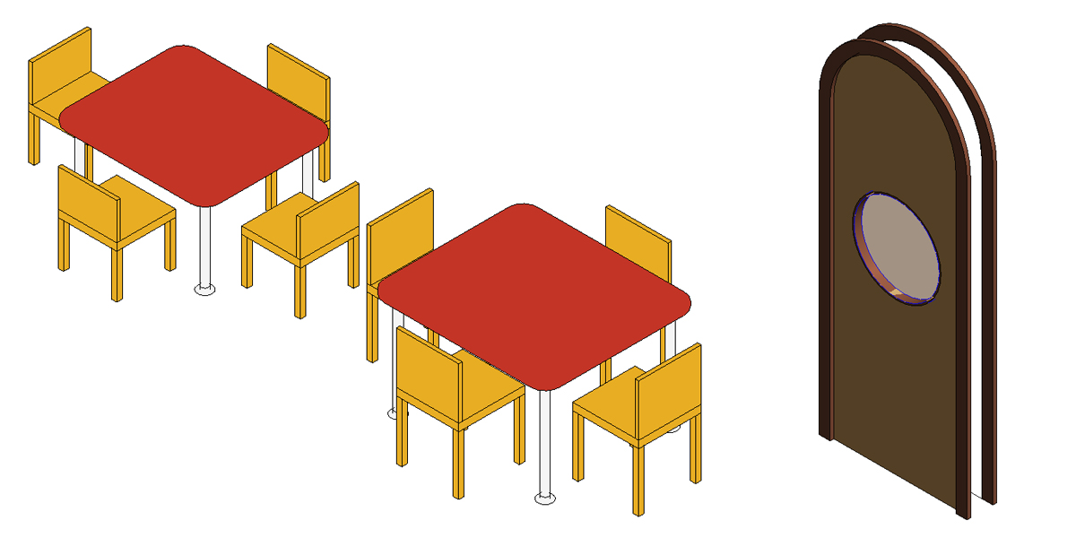
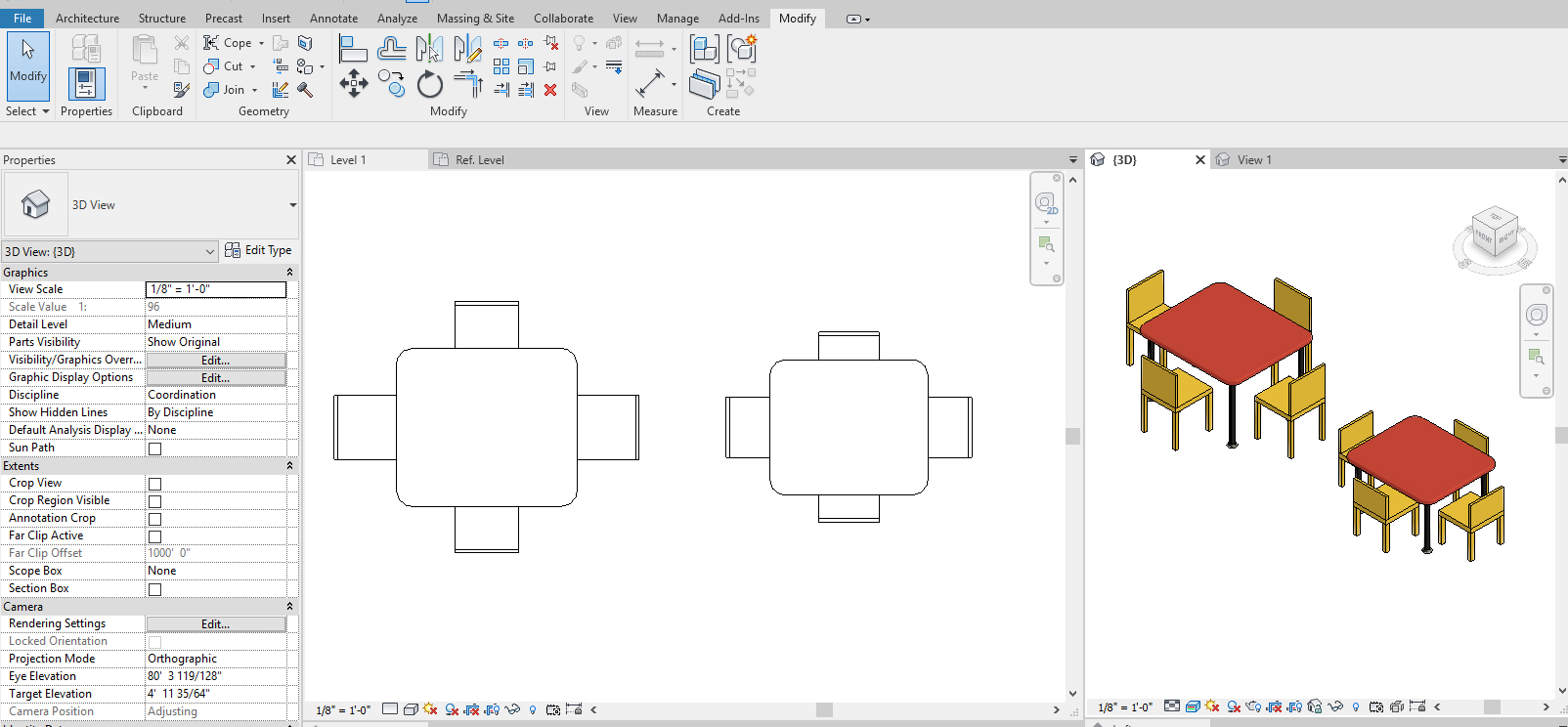
At the end of the session, students can create the graphics below.
 Lecture Contents
(CO1) Understand a nested Revit family and how it works
For more information about a Family with Nested components, please read this guide on Family and Nested components from Autodesk.
You can nest(insert) families within other families to create new families that contain the combined family geometry.
Rather than creating a furniture family from scratch, you can create the combination-furniture family by loading legs, arms, back supports, and more into a furniture family.
To nest families in another family, create or open a host family, and then load and insert instances of one or more family types into it. The host family can be a new family of an existing family.
Below example from Teknion Planning Tool.com.
(CO2) Create a chair and table set with nested Revit families
In this tutorial, students will practice creating a simple furniture set family nested with two types of chairs and a table with modifiable materials parameters.
Add components in a family file
- [STEP 1] Open Revit application, Click [NEW] from [FILE] menu > Click [FAMILY] > Open [ENGLISH-IMPERIAL] > Click [Furniture System.rft] > Click [OPEN].
- [STEP 2] Make the view to a tile view by pressing [WT].
- [STEP 3] Save the file in your project folder by [CTRL+S].
- [STEP 4] Click [LOAD FAMILY] from [INSERT] tab, under [LOAD FROM LIBRARY] panel. Load a table and a chair that you created from the last session
- [STEP 5] Place the table and the chair that you created by clicking [COMPONENT] from the [CREATE] tab, under the [MODEL] panel. Please place it slightly off the center reference lines because we need to align and lock the component.
- [STEP 6] Align and lock the components on the center reference lines.
- [STEP 7] Draw four Reference Planes on the [REF. LEVEL] plan view.
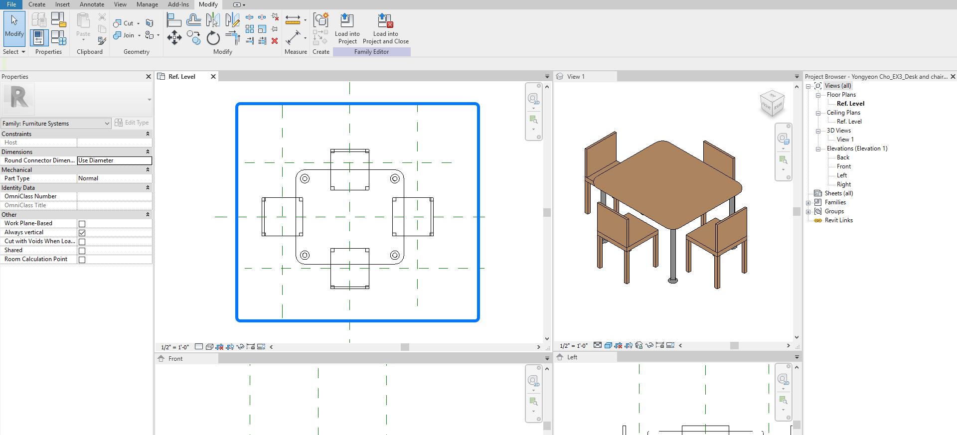
- [STEP 8] Align the back of all chairs to the near reference lines and make them lock.
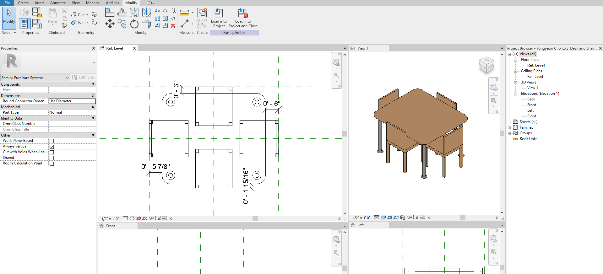
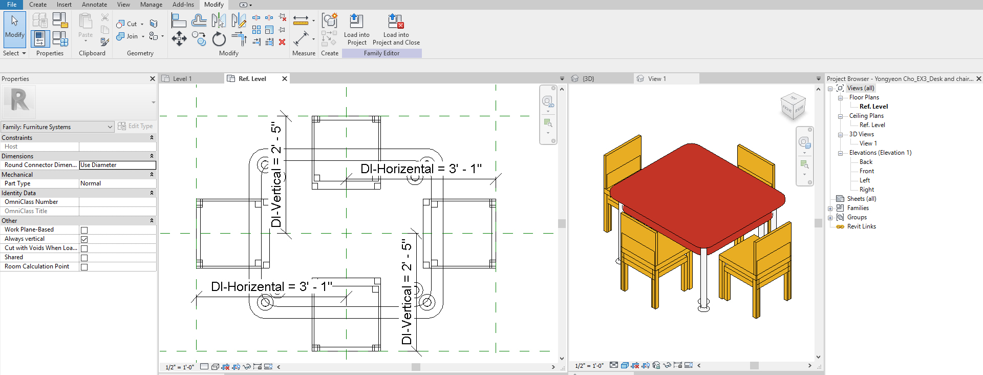
- [STEP 9] Click only Horizontal dimensions and add parameter by clicking [PARAMETER PROPERTIES] > Name [DI-HORIZONTAL] and click [INSTANCE] > click [OK].
- [STEP 10] Click only Vertical dimensions and add parameter by clicking [PARAMETER PROPERTIES] > Name [DI-VERTICAL] and click [INSTANCE] > click [OK].

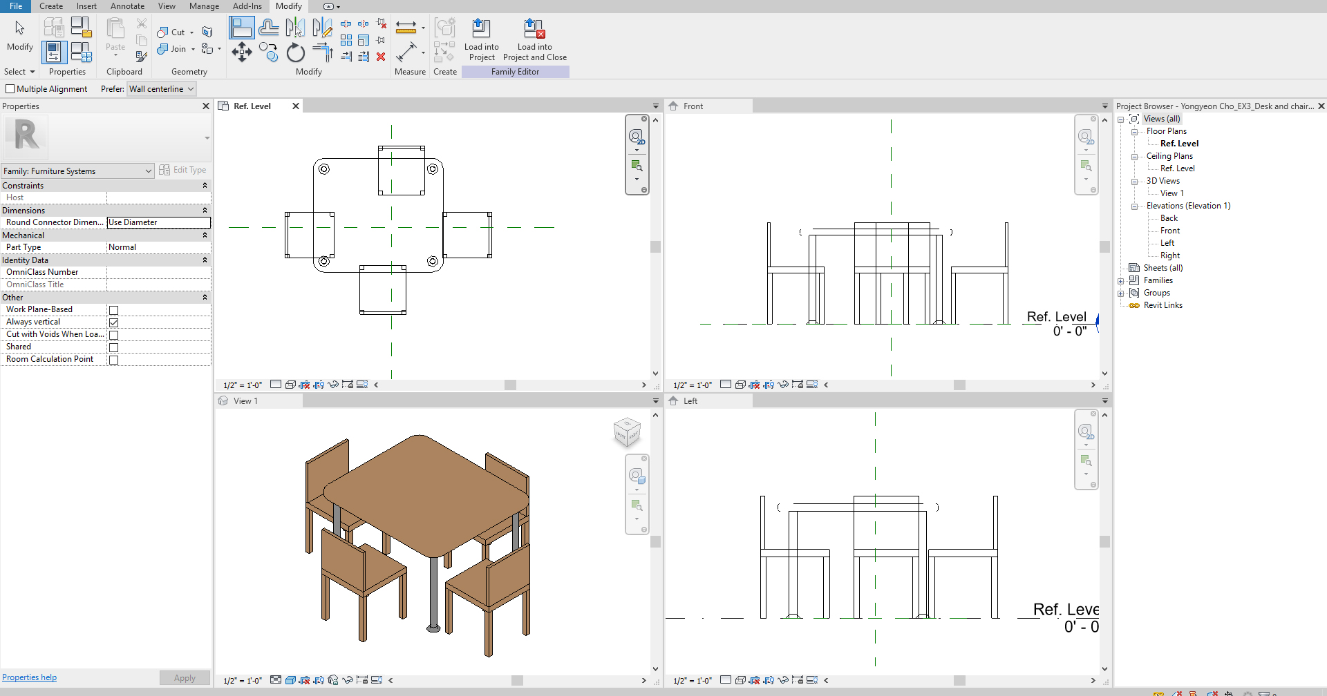
- [STEP 11] Load this family to a project to confirm the family works okay.
- Click [FILE] on the menu
- Click [NEW]
- Click [PROJECT]
- Select [IMPERIAL-ARCHITECTURAL TEMPLATE]
- Click [OK]
- Click [COMPONENT] from [ARCHITECTURE] tab, under [BUILD] panel
- Click [LOAD FAMILY] from [MODIFY/PLACE COMPONENT], under [MODE] panel
- Click the chair and table set family
- Place the family on [LEVEL 1] Floor plan.
You can confirm whether the chairs are movable or not by adjusting the arrows.
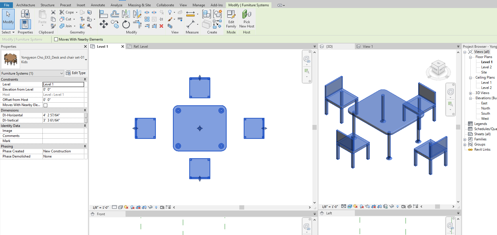
Open [EDIT TYPE] from [PROPERTIES] palette to see what properties we can edit to create other types. However, the only property we can adjust is [DEFAULT ELEVATION]. In the next tutorial, students can edit material parameters and visible parameters.
Add material and finish parameters
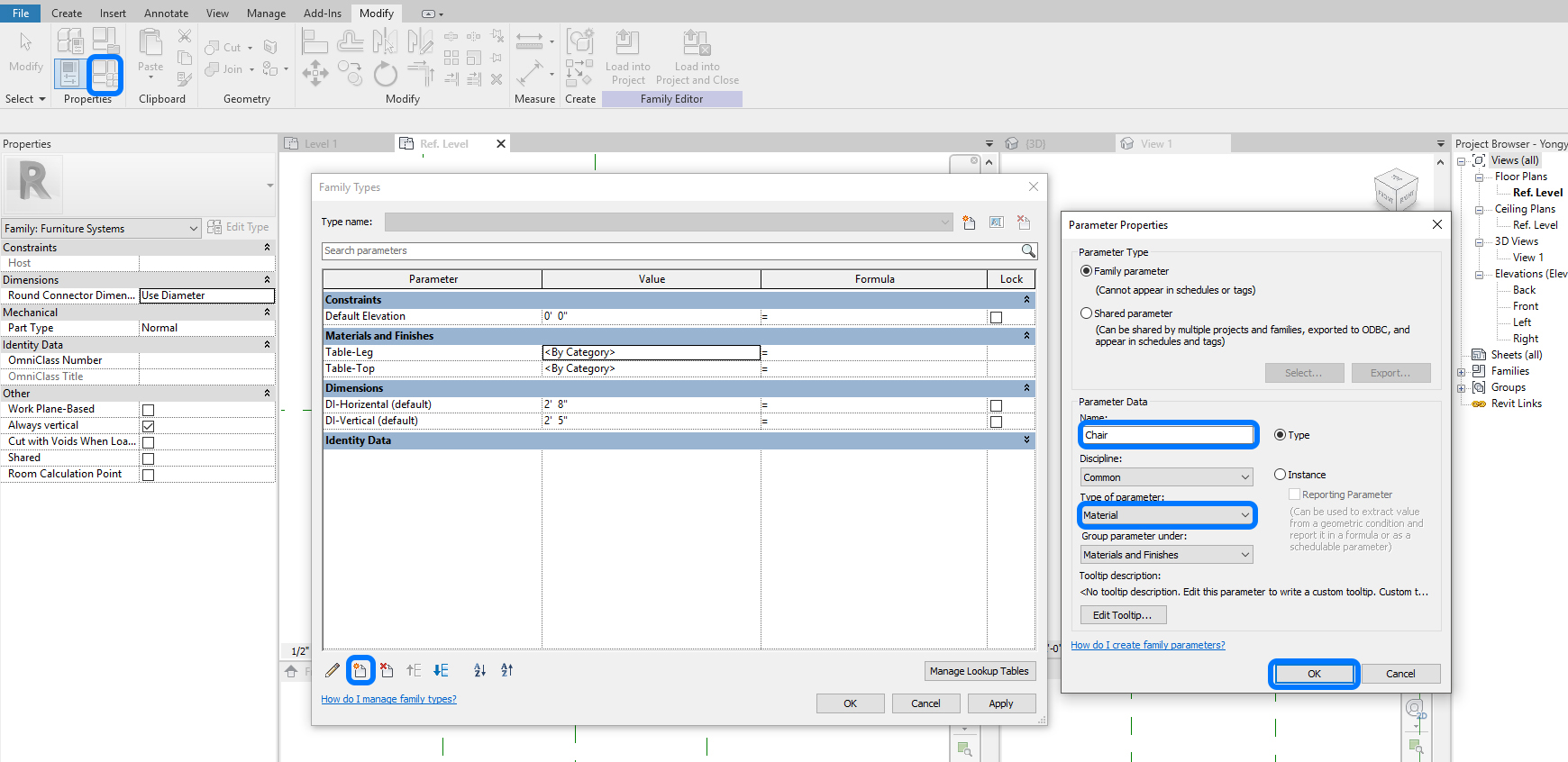
- [STEP 1] Open [FAMILY TYPES] from [MODIFY] tab, under [PROPERTIES] panel.
- [STEP 2] Click [NEW] > Add name [TABLE-TOP], update Type of parameter to [MATERIAL].
Repeat this step for [TABLE-LEG] and [CHAIR] > Then click [OK] to finish.
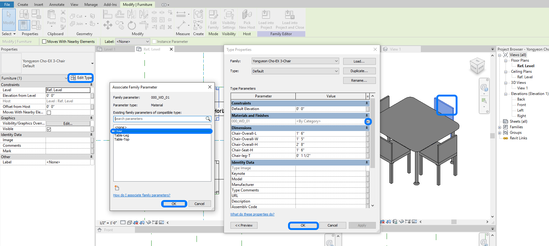
- [STEP 3] Select the table > Click [EDIT TYPE] from [PROPERTIES] > Click a small box by the Table-Top > Click [TABLE-TOP] on [ASSOCIATE FAMILY PARAMETER] > then [TABLE-TOP] will gray out.
Repeat this step for [TABLE-LEG] and [CHAIR].
- [STEP 4] Open [FAMILY TYPES] and apply materials on the parameters. You can use the existing materials or create new materials.
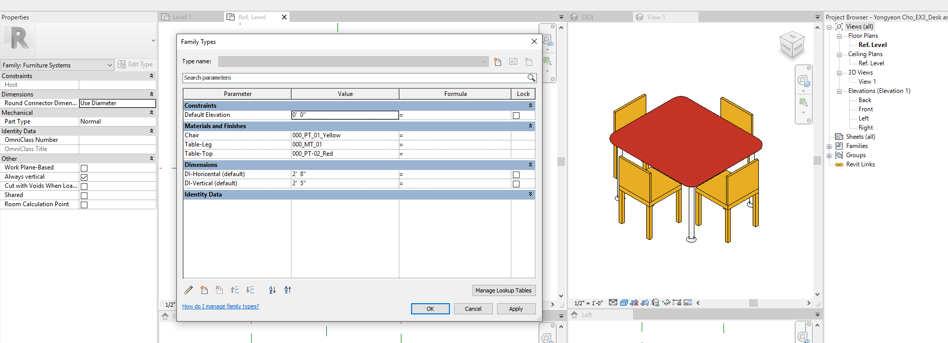
- [STEP 5] Load this updated family to the project by clicking [LOAD INTO PROJECT] and click [OVERRIDE THE EXISTING VERSION].
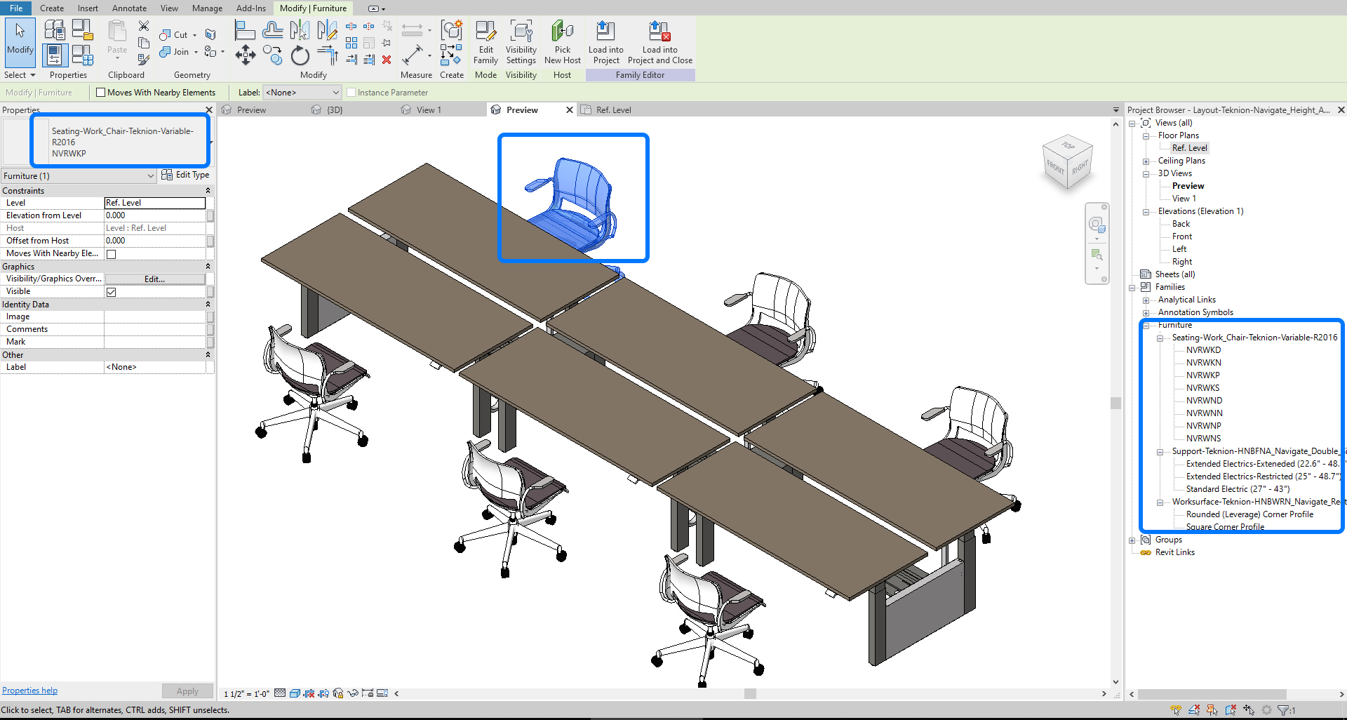
- [STEP 6] Select the chair and table set > click [EDIT TYPE], and you can see what parameters are available to modify. You can create a new type by clicking [DUPLICATE].
Add visible parameters
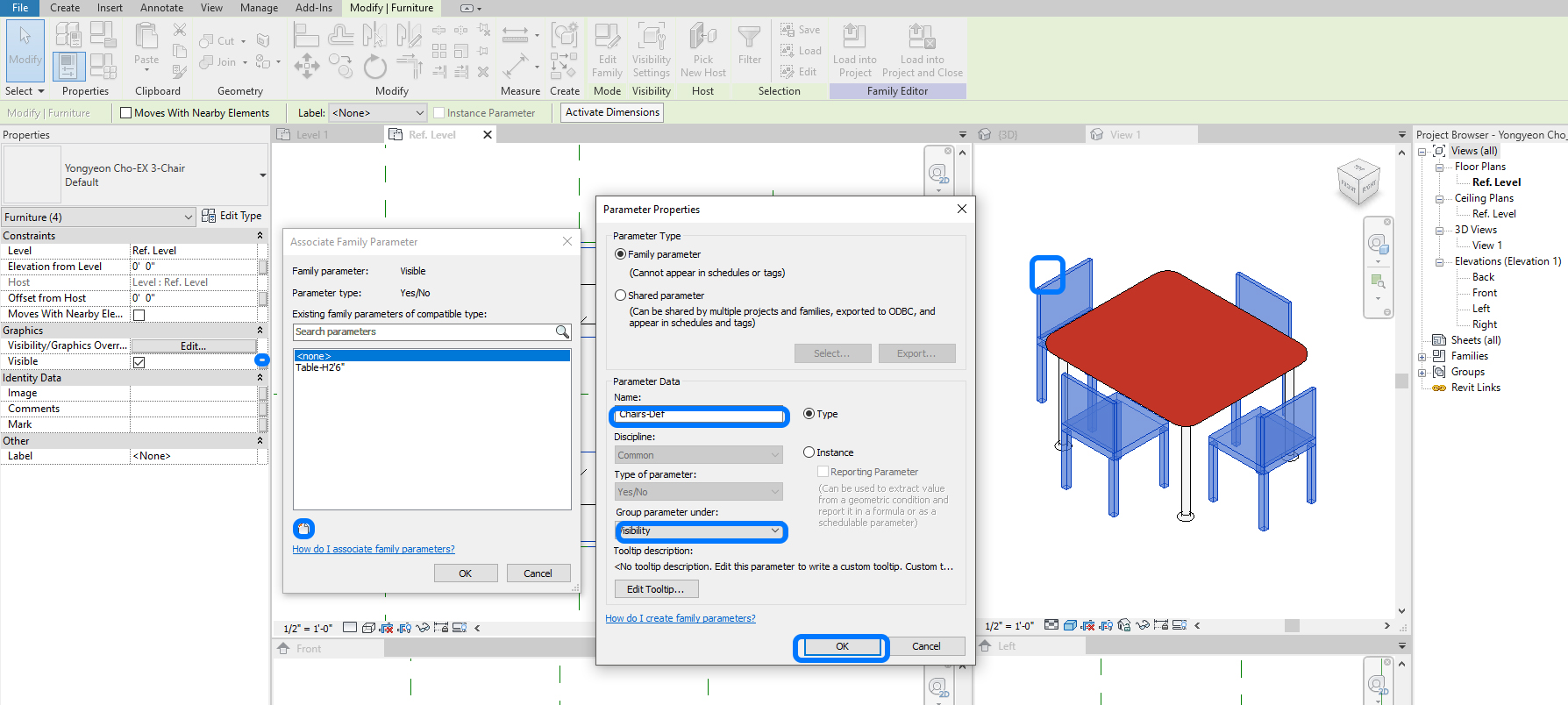
- [STEP 1] Select [TABLE] > Click the small box next to visible on [PROPERTIES] to open [ASSOCIATE FAMILY PARAMETER] > Click [NEW] > Add name [Table-H2’6″] confirm the Type of parameter is [YES/NO], group parameter under [VISIBILITY].
- [STEP 2] Select all [CHAIRS] > Click the small box next to visible on [PROPERTIES] to open [ASSOCIATE FAMILY PARAMETER] > Click [NEW] > Add name [Chairs-Def] confirm the Type of parameter is [YES/NO], group parameter under [VISIBILITY].
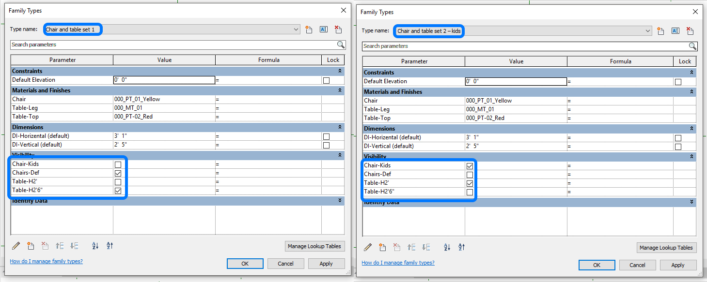
- [STEP 3] Open [FAMILY TYPES] > click [NEW] type to add a new type > add name [Chair and table set 1] > Click [OK] to finish > Click [APPLY].
- [STEP 4] Click [NEW] type again > add name [Chair and table set 2 – kids] > Click [OK] > uncheck both [Chair-Def] and [Table-H2’6”].
- [STEP 5] Click [COMPONENT] > Select the table family from [PROPERTIES] > Click [EDIT TYPE] > click [DUPLICATE] > add name [L3’xW3’6″xH2′] > adjust dimension accordingly.
- [STEP 6] Place the table and align it with the center reference planes.
- [STEP 7] Click [COMPONENT] > Select the chair family from [PROPERTIES] > Click [EDIT TYPE] click [DUPLICATE] > add name [KIDS] > adjust dimension accordingly.
- [STEP 8] Place the chairs and align them with the four reference planes.
- [STEP 9] Define the visible parameters for both the small table and the small chairs.
- [STEP 10] Confirm Family types for both set 1 and set 2-kids.
- [STEP 11] Load this family into the project and override.
- [STEP 12] Add the new type to confirm the two types are different.
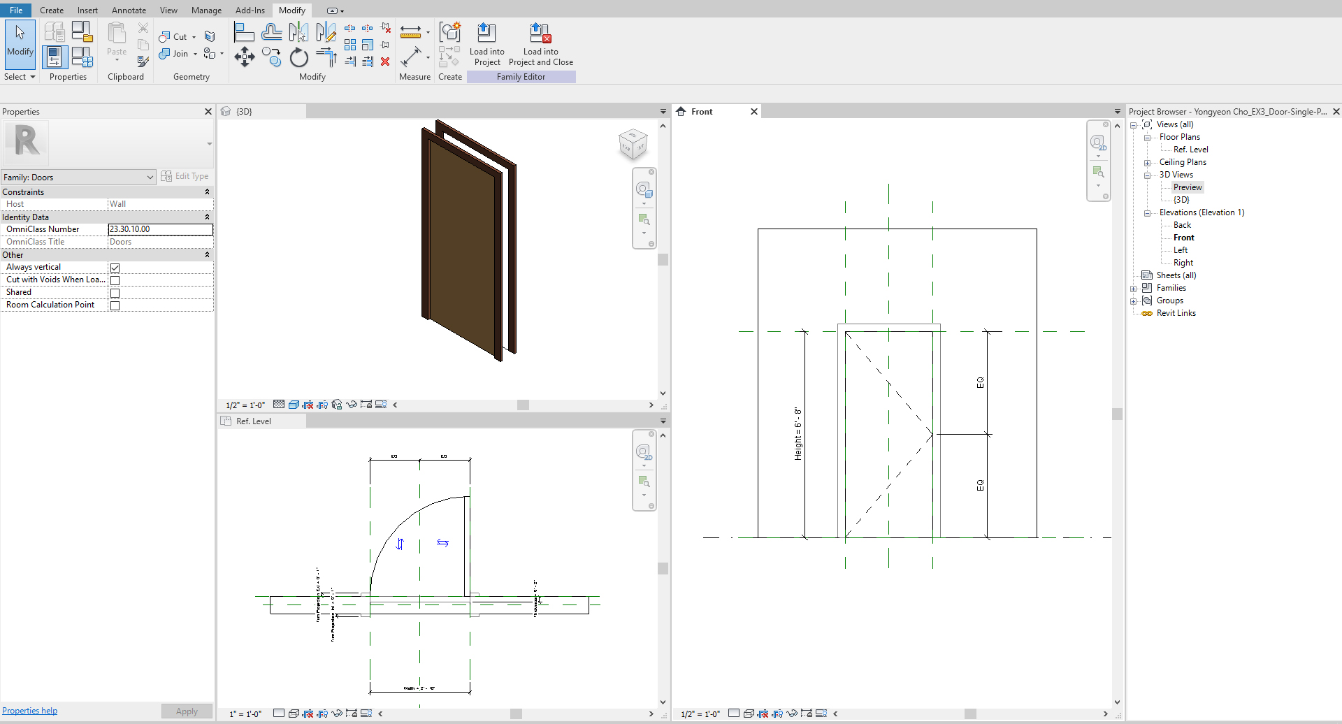
(CO3) Modify a door family
In this tutorial, students will practice creating a simple furniture set family nested two types of chairs and a table with modifiable materials parameters.
Edit a door family
- [STEP 1] Open the basic door file.
- Click [FILE].
- Click [OPEN].
- Click [FAMILY].
- Find [LIBRARIES\US IMPERIAL\DOORS] folder.
- Click [Door-Single-Panel.rfa].
- Open.
- [STEP 2] Save the family file in your project folder.
- Click [FILE].
- Click [SAVE AS].
- Click [FAMILY].
- Find [your project folder].
- File name [Firstname Lastname_EX3_Door-Single-Panel.rfa].
- Click [SAVE].
- [STEP 3] Open [Ref.Level], [FRONT], and [3D] views. Make a tile view by pressing [WT].
- [STEP 4] Edit the door trims.
- Click the front door trim on the front view.
- Click [EDIT EXTRUSION] from [MODIFY/TRIM] tab, under [MODE] panel.
- Edit the sketches with Draw tools and use the trim tool. Make sure the edges and lines are locked.
- Click [GREEN CHECKMARK] to finish the sketch.
- Click the backside door trim and edit with the draw tools.
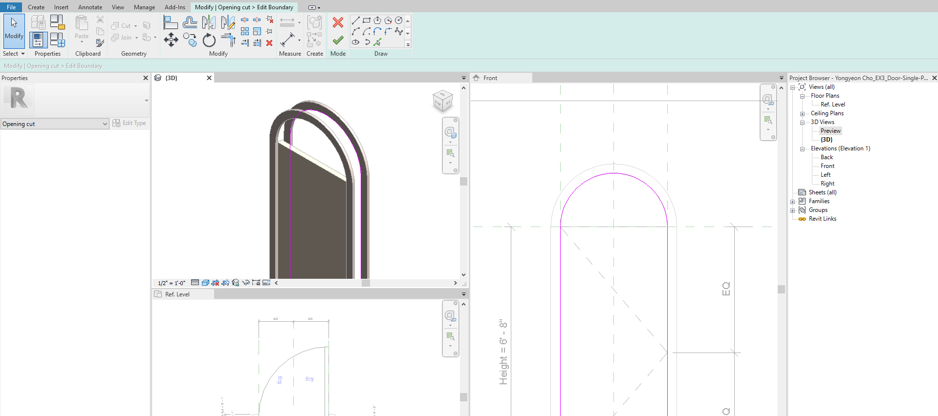
- [STEP 5] Edit Opening cut.
- Click [OPENING CUT] on the 3D view.
- Click [EDIT SKETCH] from the [MODIFY/OPENING CUT] tab, under the [MODE] panel.
- use the draw tool and the trim tool to edit the lines to align with the inside of the trim. Make sure the edges and lines are locked.
- Click [GREEN CHECKMARK] to finish the sketch.
- [STEP 6] Edit Door.
- Click the [DOOR] on the 3D view.
- Click [EDIT EXTRUSION] from [MODIFY/PANEL] tab, under [MODE] panel.
- use the draw tool and the trim tool to edit the lines to align with the inside of the trim. Make sure the edges and lines are locked.
- Click [GREEN CHECKMARK] to finish the sketch.
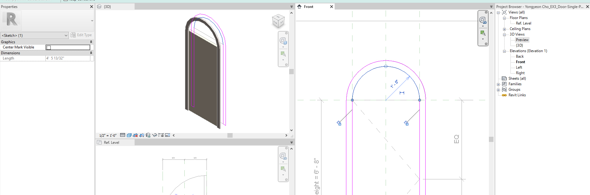
- [STEP 7] Add door window on the door panel.
- Add a reference plane for the door window height.
- Add a dimension from the floor level and add a parameter.
- Create a void extrusion with the drawing tool, check [CENTER MARK VISIBLE], and align with the center line and the Door Window H reference plane.
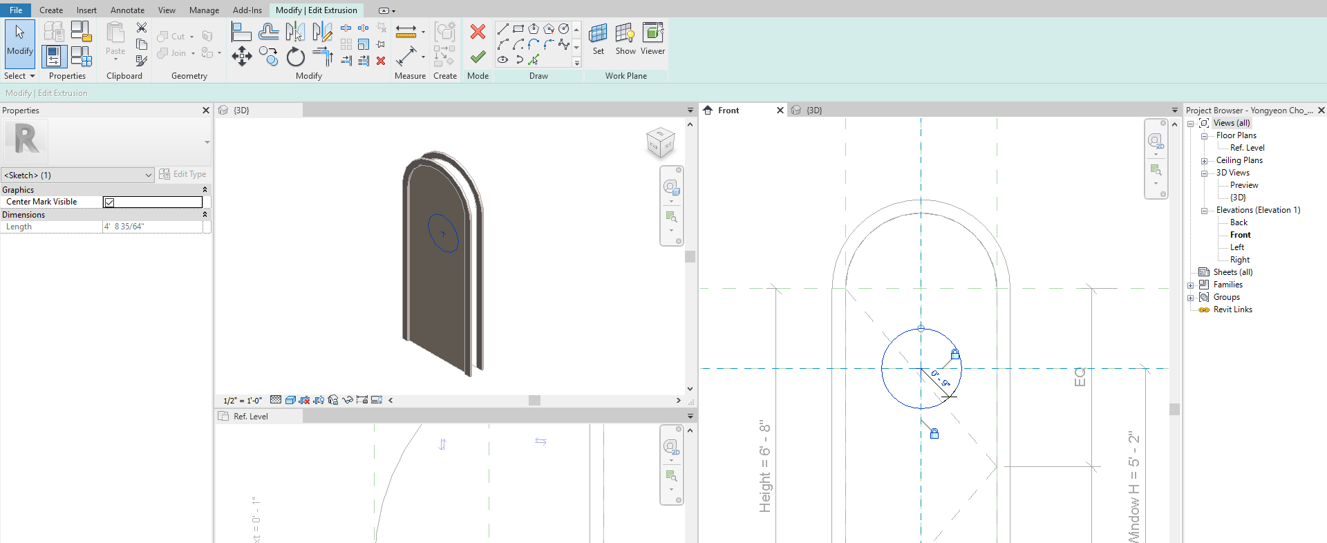
- Adjust a void extrusion height on the Ref. Level and lock the end and start points.
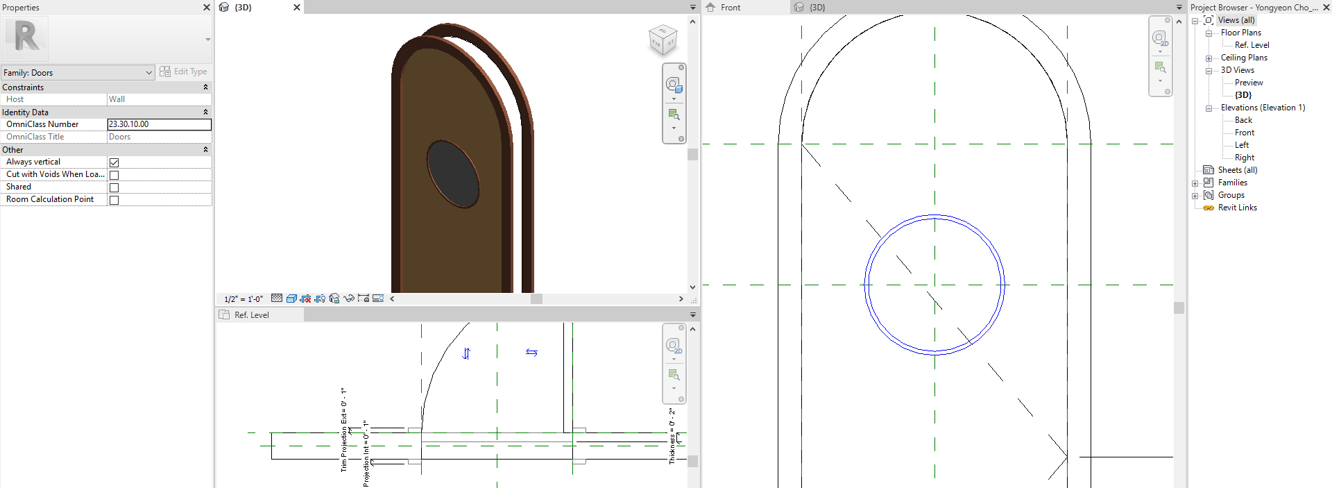
- Click [CUT] from the [MODIFY] tab, click the void and then click the door panel to cut the void.
- Add a window trim with [SWEEP] from [CREATE] tab, under [FORMS] panel.
- Add material for the window trim.
- Add a window with [EXTRUSION] from [CREATE] tab, under [FORMS] panel.
- Add material for the window.
- [STEP 8] Update [VISIBILITY/GRAPHICS OVERRIDE].
- Select the door window trim and the window.
- Click [EDIT] on [VISIBILITY/GRAPHICS OVERRIDE].
- Uncheck [PLAN/RCP] and [WHEN CUT IN PLAN/RCP].
- Click [OK].
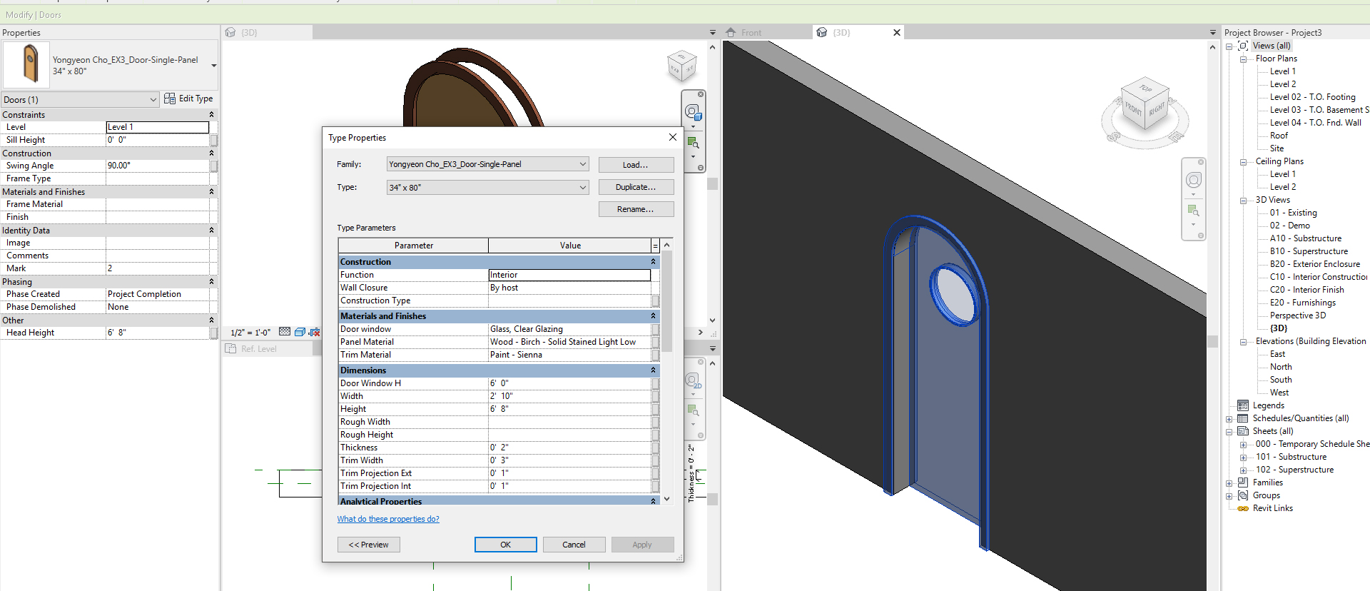
- [STEP 9] Test the family in a Project and edit the parameters that you added.
 References
Autodesk Help. (May 13, 2020). Create a Family with Nested Components. Retrieved December 23, 2021, from https://knowledge.autodesk.com/support/revit/learn-explore/caas/CloudHelp/cloudhelp/2018/ENU/Revit-Customize/files/GUID-9C9DCF9D-8251-451C-8767-42A9557861FF-htm.html
Teknion. (n.d.). Revit Symbols Library – Teknion. Retrieved December 23, 2021, from https://www.teknion.com/tools/tools/revit-symbols-library2
