
Part Three. Advanced Modeling
Chapter 9. Revit – Family parameter
Upon completing this session, students will be able to:
- (CO 1) Understand parameters in Revit family modeling
- (CO 2) Create a simple chair with parameters
- (CO 3) Create a simple table with parameters
 Session Highlights
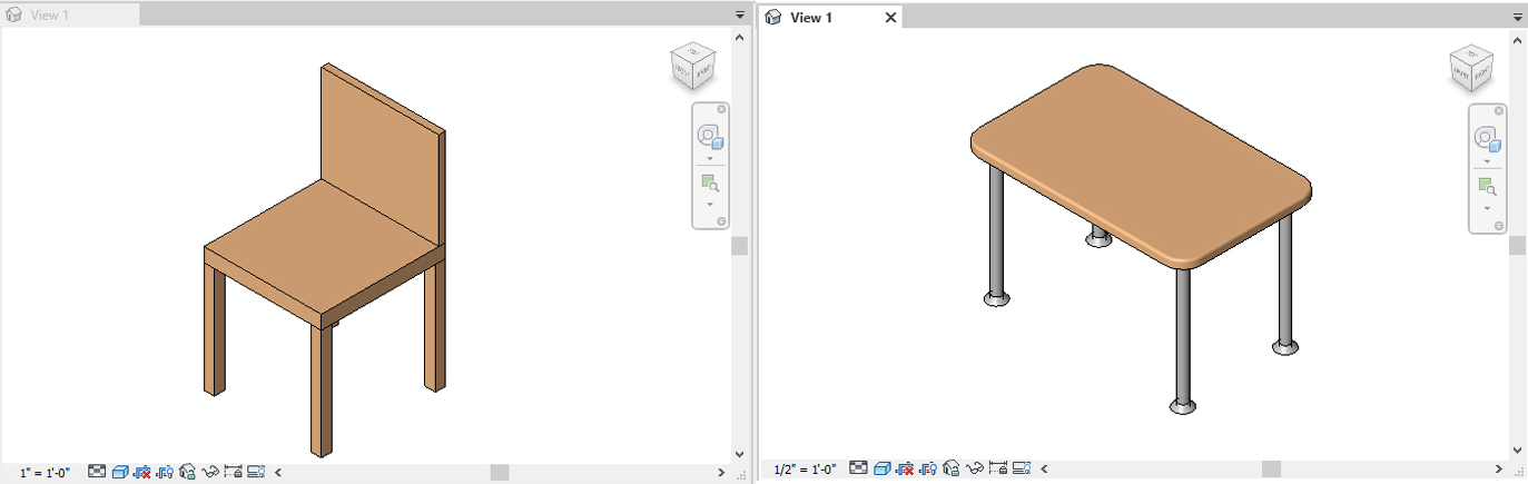
At the end of the session, students will be able to create the graphics below.
 Lecture Contents
(CO1) Understand parameters in Revit family modeling
About Parameters
You can create parameters for a project and any element or component category in the project.
Parameters that you create display in the Properties palette or Type Properties dialog under the group you define and with the values you define.
For more information about Revit Parameters, please read this guide on Revit Parameters from Autodesk.
Family Parameters
Family parameters control variable values of the family, such as dimensions (Width, Height, and Depth) or materials. They are specific to the family.
A family parameter can also be used to control a parameter in a nested family by associating the parameter in the host family to the parameter in the nested family.
By adding new parameters, you have more control over the information contained in each family instance or type. You can create dynamic family types for increased flexibility within the model.
For more information about Revit Family Parameters, please read this guide on Revit Family Parameters from Autodesk.
(CO2) Create a simple chair with parameters
In this tutorial, students will practice creating a simple chair family with parameters that can change the dimensions and materials.
To create a simple chair family
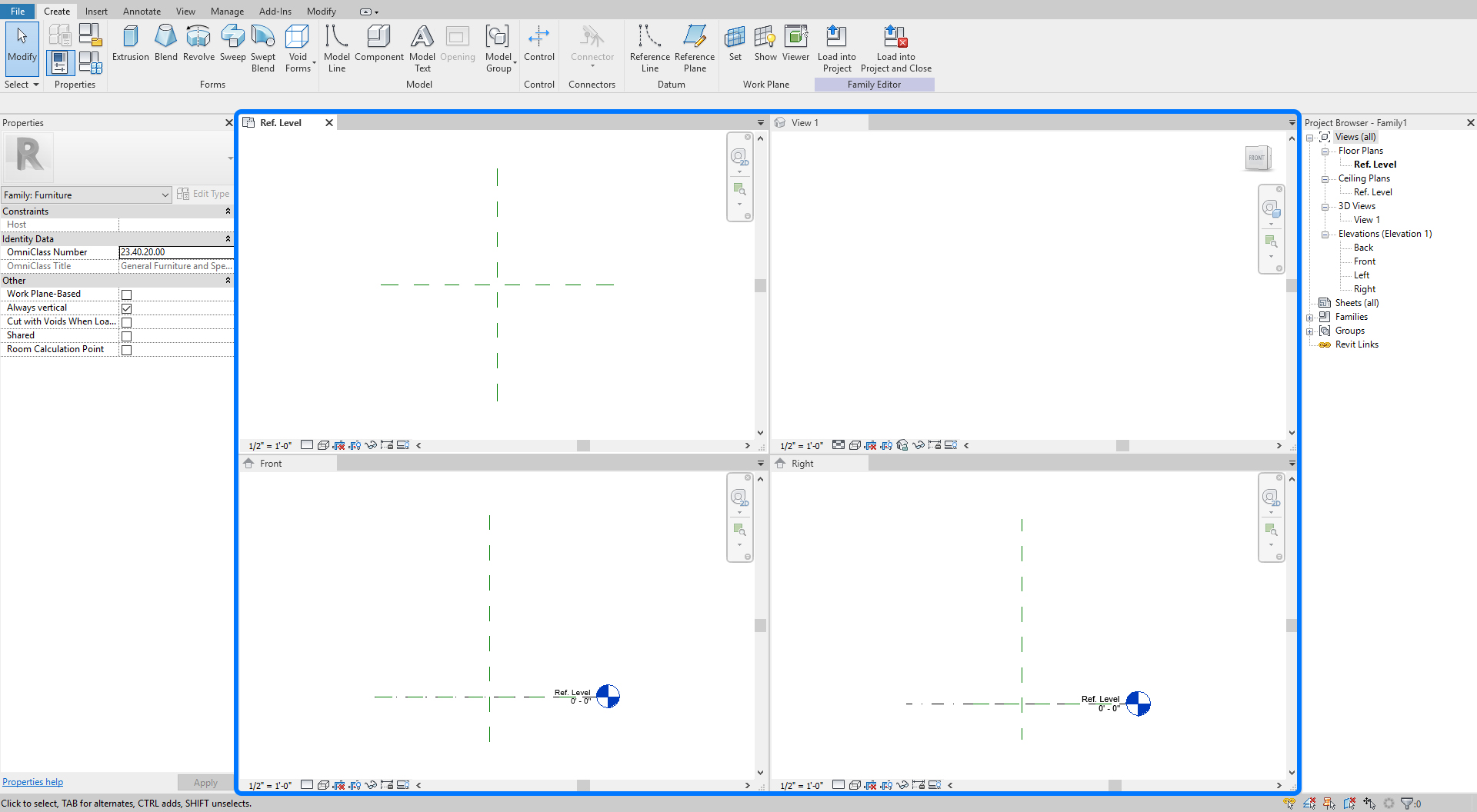
- [STEP 1] Open [Revit] Application, In this tutorial, the instructor use Revit 2021.
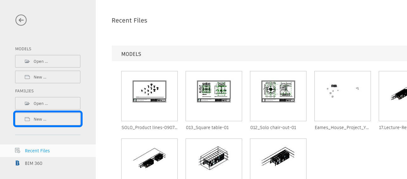
- [STEP 2] Click [New … ] under [Families] category on the [Welcome] page.
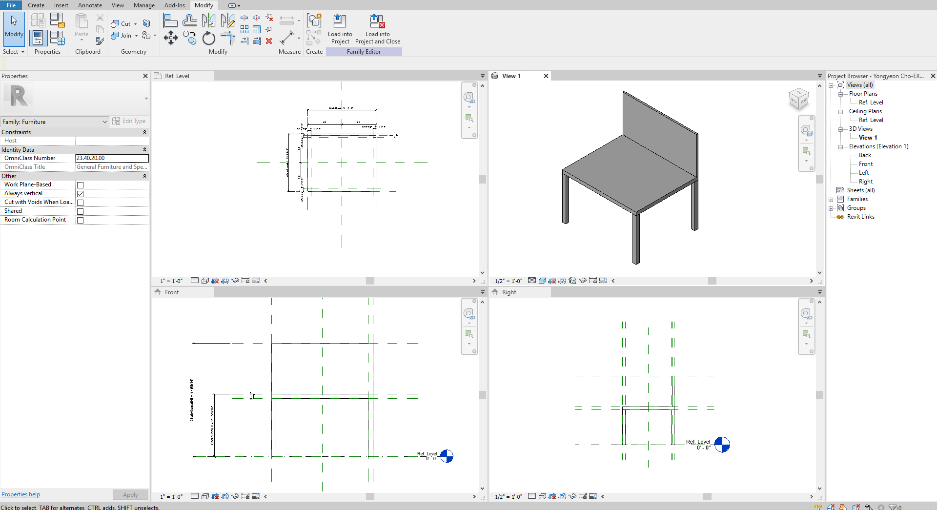
- [STEP 3] Open [English-Imperial] folder, select [Furniture.rft], and click [Open], then you will see the four views. Make a tile window view [WT] to see all
[Save] the file before you start. [First_Lastname_EX3_Chair].
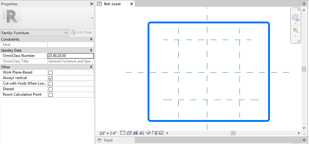
- [STEP 4] Select [Reference Plane] from [Create] tab, under [Datum].
- [STEP 5] Draw four lines near the center lines on the [Ref. Level] plan view. The center lines are locked—these four lines for the overall width and length of the chair. You do not need to draw the reference plans precisely.
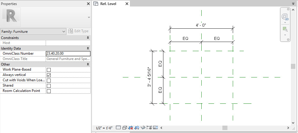
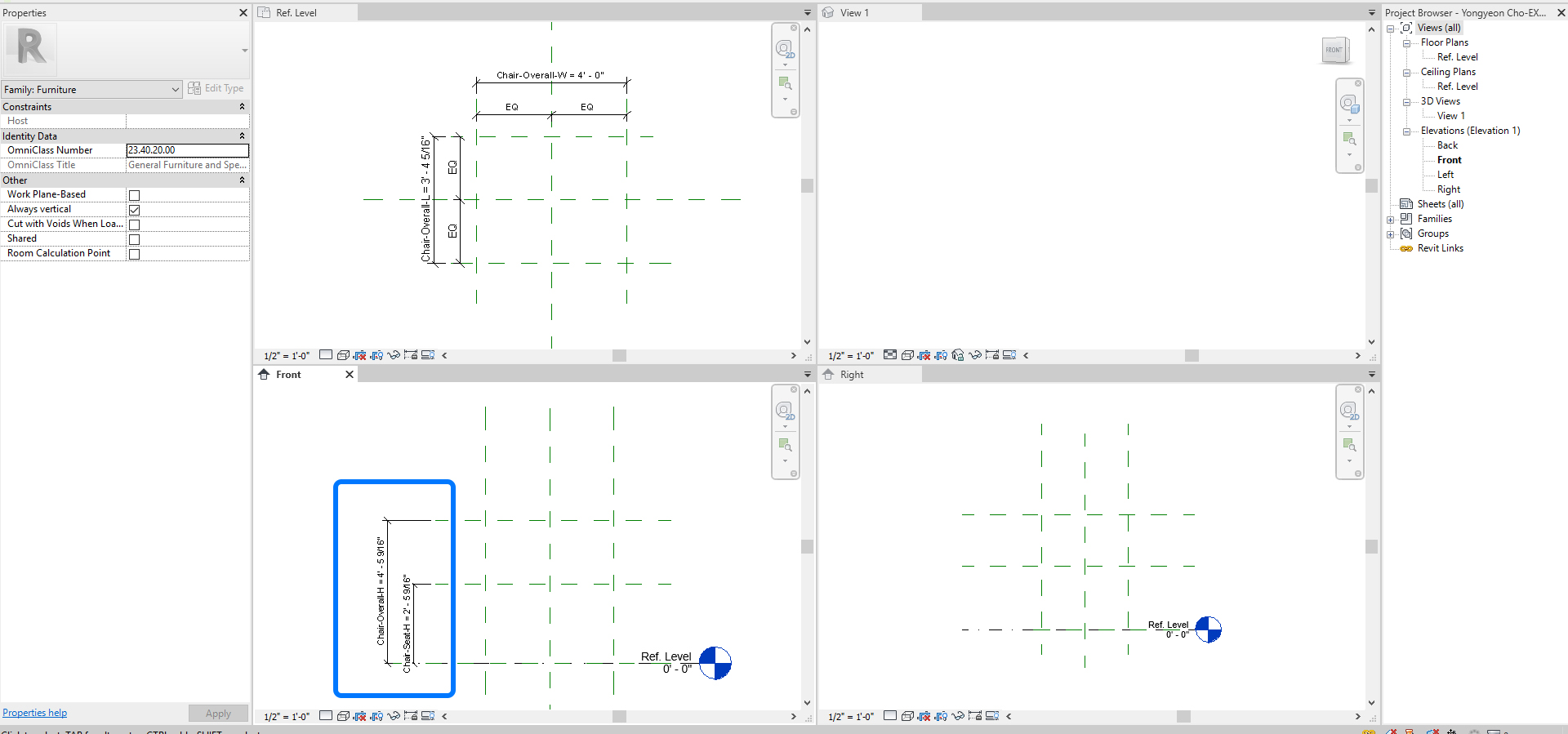
- [STEP 6] Click [Aligned Dimension] from [Annotate] tab, under [Dimension].
or, type [DI] and create dimension for overall all dimensions and the center dimensions with Equal.
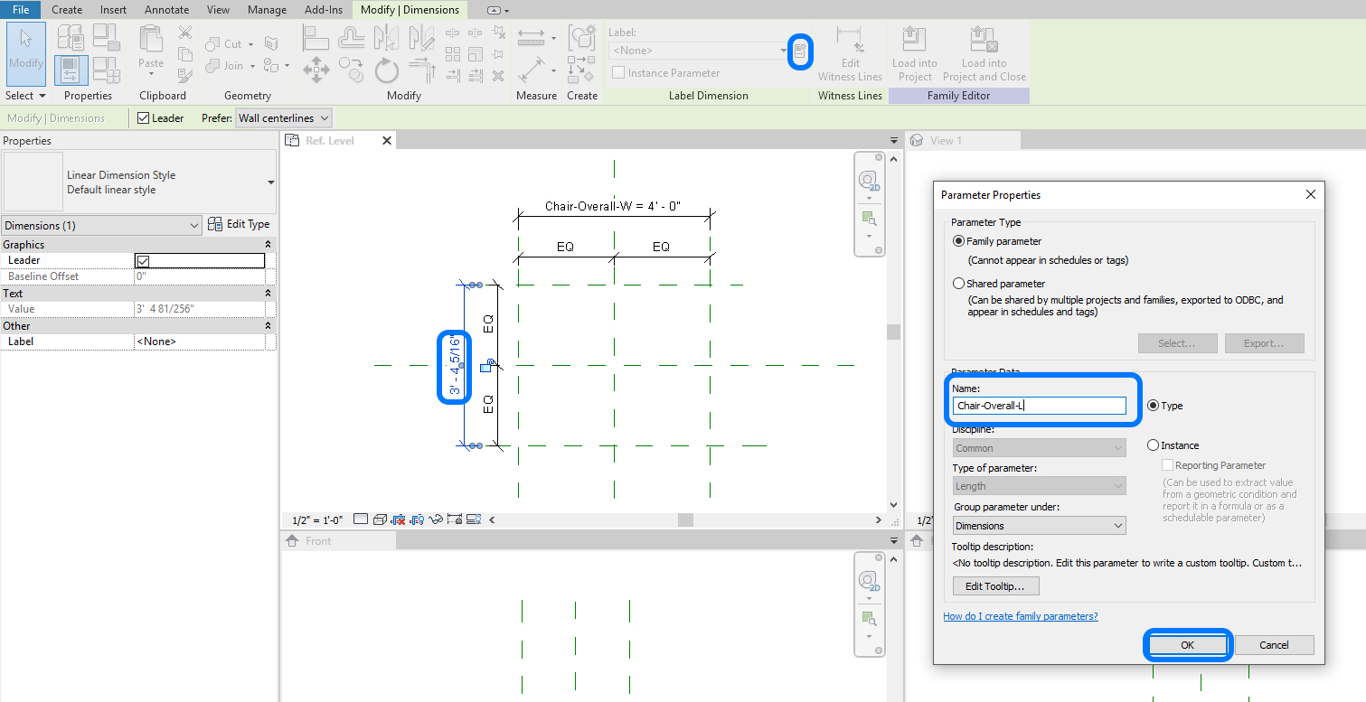
- [STEP 7] Click the overall width dimension,click [Parameter Properties] from [Modify/Dimensions], under [Label Dimension].
Then add Name [Chair-Overall-W] and click [OK] to finish.
Repeat this step for [Chair-Overall-L].
- [STEP 8] Add reference planes for heights.
- Select [Reference Plane] from [Create] tab, under [Datum] panel
or, [RP]. - draw two lines on the [Front] view.
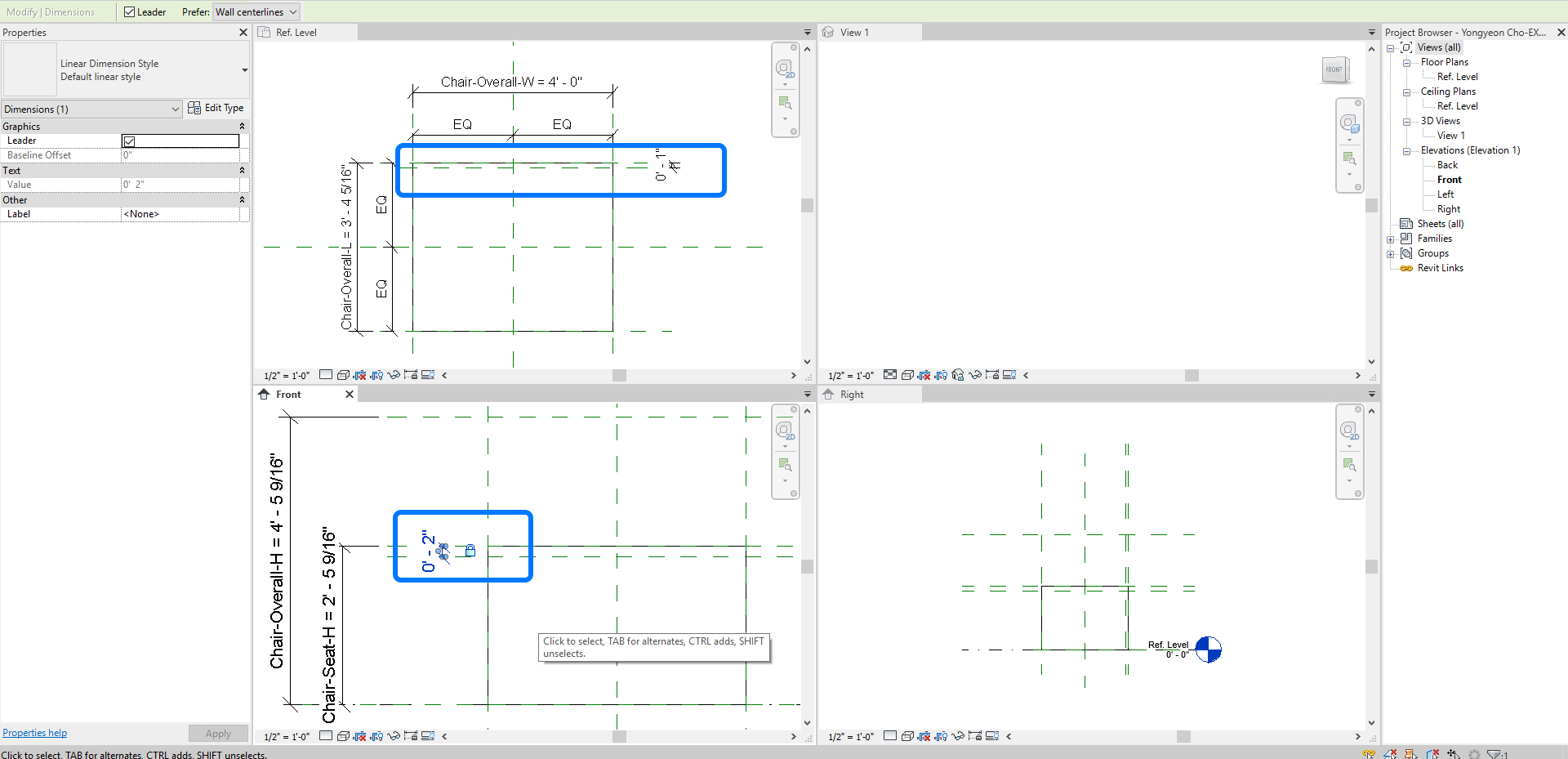
- add dimensions for [Chair seat height] and [Chair overall height].
- define the parameter name on [Parameter Properties].
- Chair-Seat-H.
- Chair-Overall-H.
- Select [Reference Plane] from [Create] tab, under [Datum] panel
- [STEP 9] Add reference planes for the seat depth = 2″ and the seat back depth = 1″.
make dimensions for the depths with lock, but do not define the name.
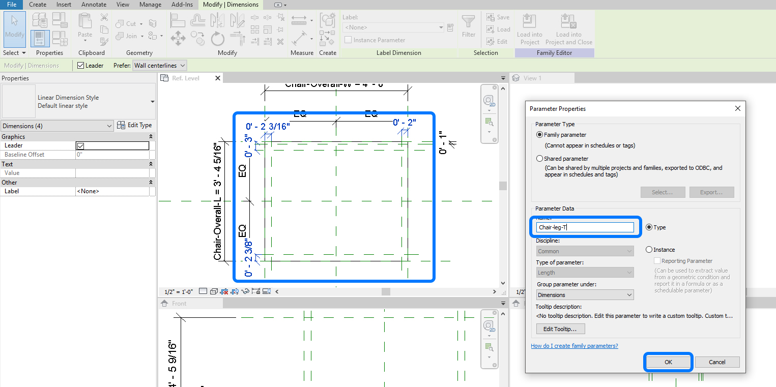
- [STEP 10] Add reference planes for chair leg thickness.
-
- Make dimensions for the leg thickness.
- Select the four dimensions together.
- Click [Parameter Properties.
- Add Name [Chair-leg-T].
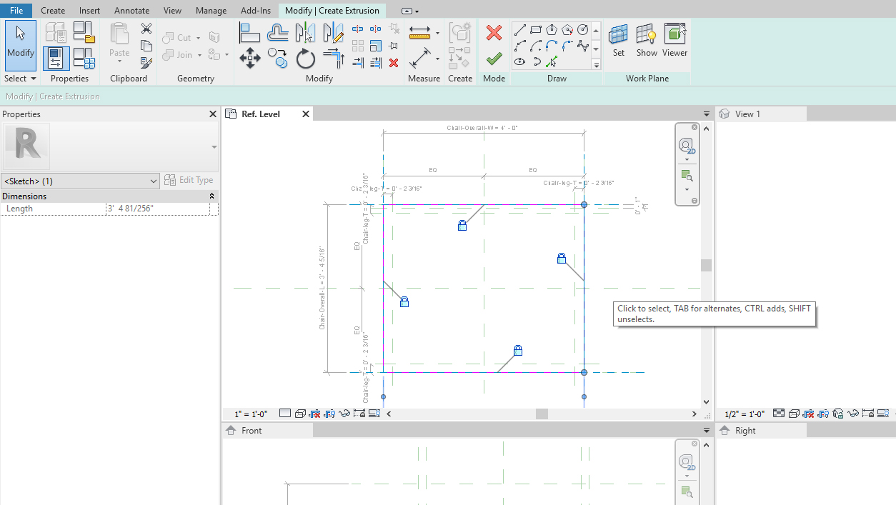
Now you are ready for modeling. If needed, please update the scale of the view.
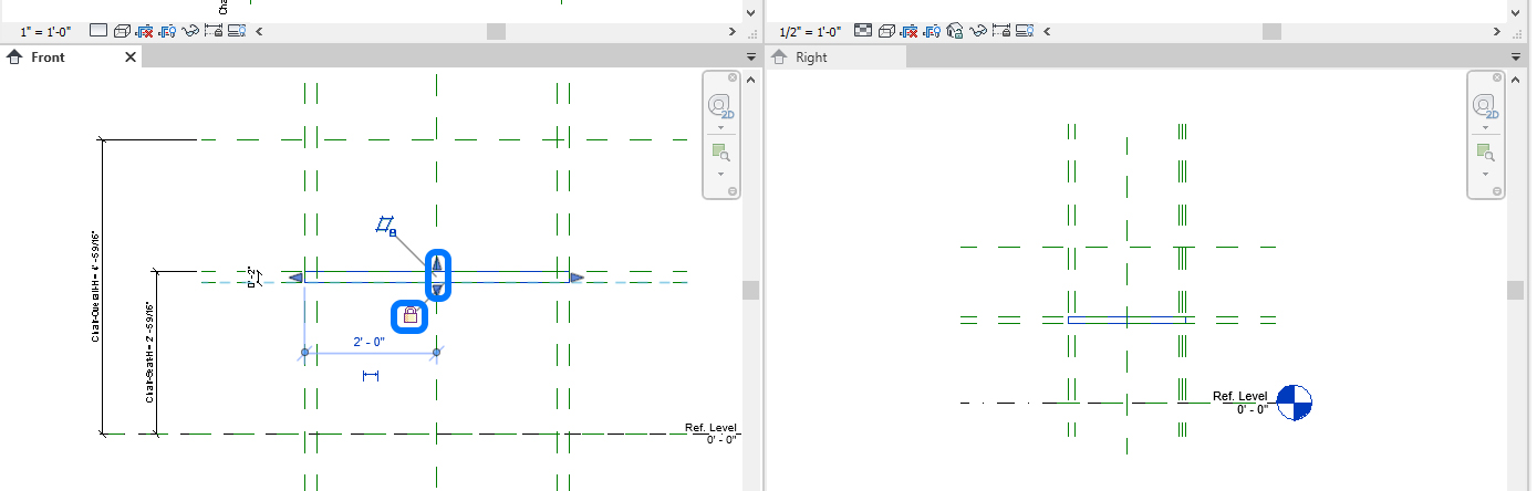
- [STEP 11] Click [Extrusion] from the [Create] tab, under the [Forms] panel, and draw lines to fit the overall dimension of the chair and lock all.
- [STEP 12] See the front view and update the seating height by adjusting the arrows. Please make it locked for both the bottom of the seat and the top of the seat. It is an essential step to accommodate parameter changes.
- [STEP 13] Repeat [STEP 11] to [STEP 12] for the chair back and chair legs.
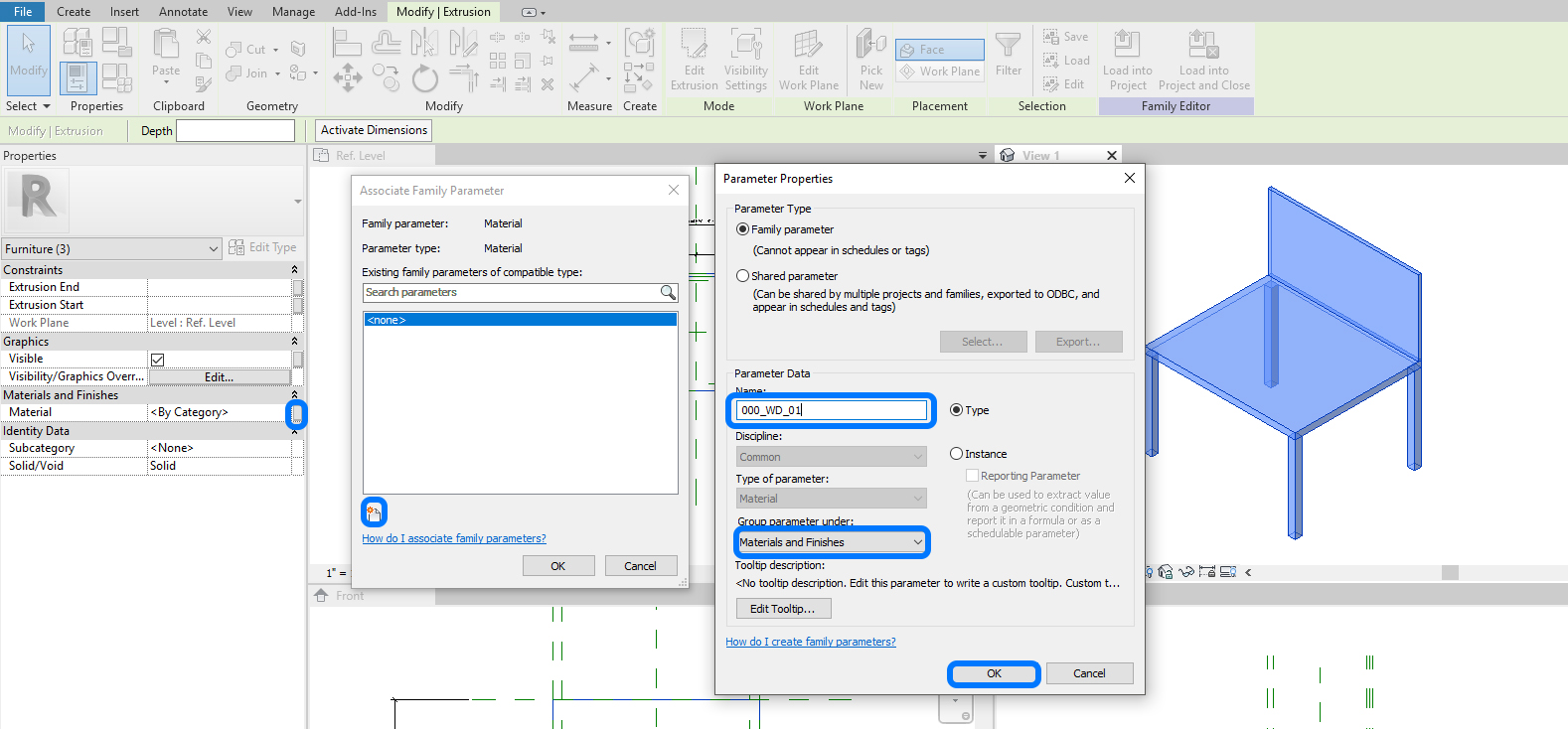
- [STEP 14] To define the material parameter.
- Select objects that you want to define a material.
- Click [associate family parameter].
- Click [New].
- Add [000_WD_01] on Name, make sure the Group parameter under [Materials and Finishes].
Note, the Name can be defined with elements (e.g., chair-legs, chair-seat).
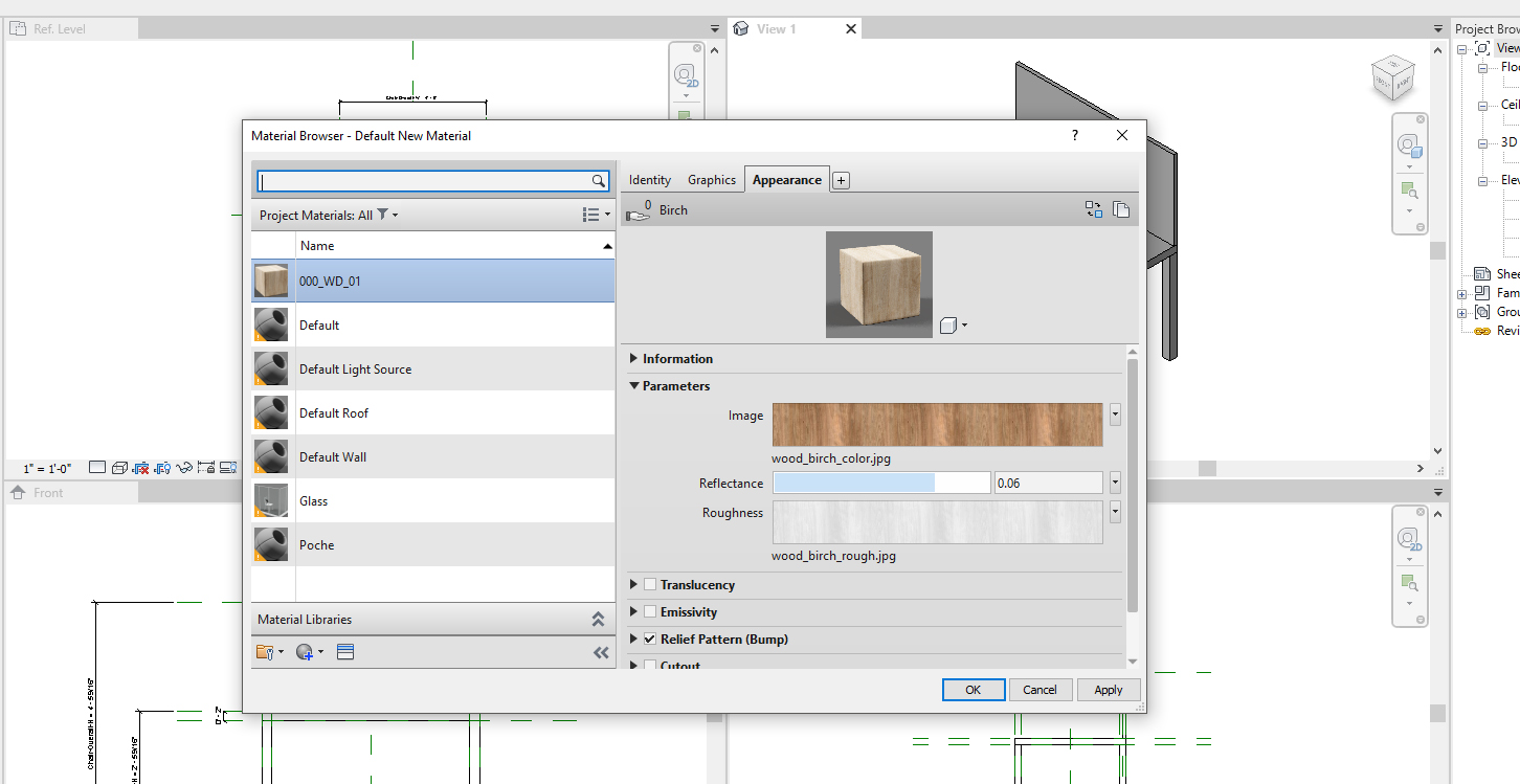
- [STEP 15] To add new material,
- click [Materials] from [Manage] tab, under [Settings] panel
- add new material, rename, apply a new appearance
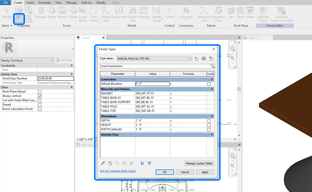
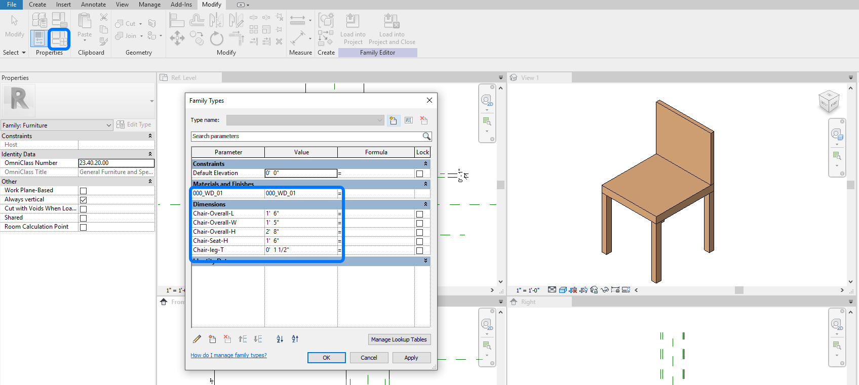
- [STEP 16] Adjust Family Types.
- Click [Family Types] from [Modify] tab, under [Properties] panel.
- Update the properties
- 000_WD_01 = 000_WD_01
- Chair-Overall-L = 1.6”
- Chair-Overall-W = 1’5″
- Chair-Overall-H = 2’8”
- Chair-Seat-H=1’6”
- Chair-leg-T=1 ½”
- Click [OK] to finish
- [STEP 17] To save a new type.
- Open [Family type]
- Click [New Type]
- Name change [Default] to save the current settings
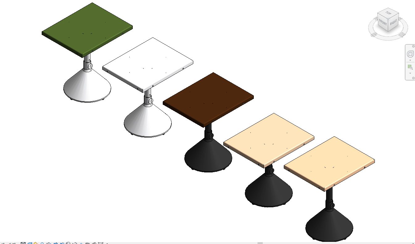
- [STEP 18] To add a new family type.
- Open [Family type]
- Change parameter values
- Click [New Type]
- Name change
- Click [OK]
(CO3) Create a simple table with parameters
In this tutorial, students will understand the basic knowledge of family parameters by creating a simple table family that can change the dimensions and materials.
To create a simple table family with round, two materials
- [STEP 1] Click [File] > click [New] > click [Family] > Open [English-Imperial] folder > select [Furniture.rft] > click [Open].
- [STEP 2] Make [Window Tile] view to see all four views once.
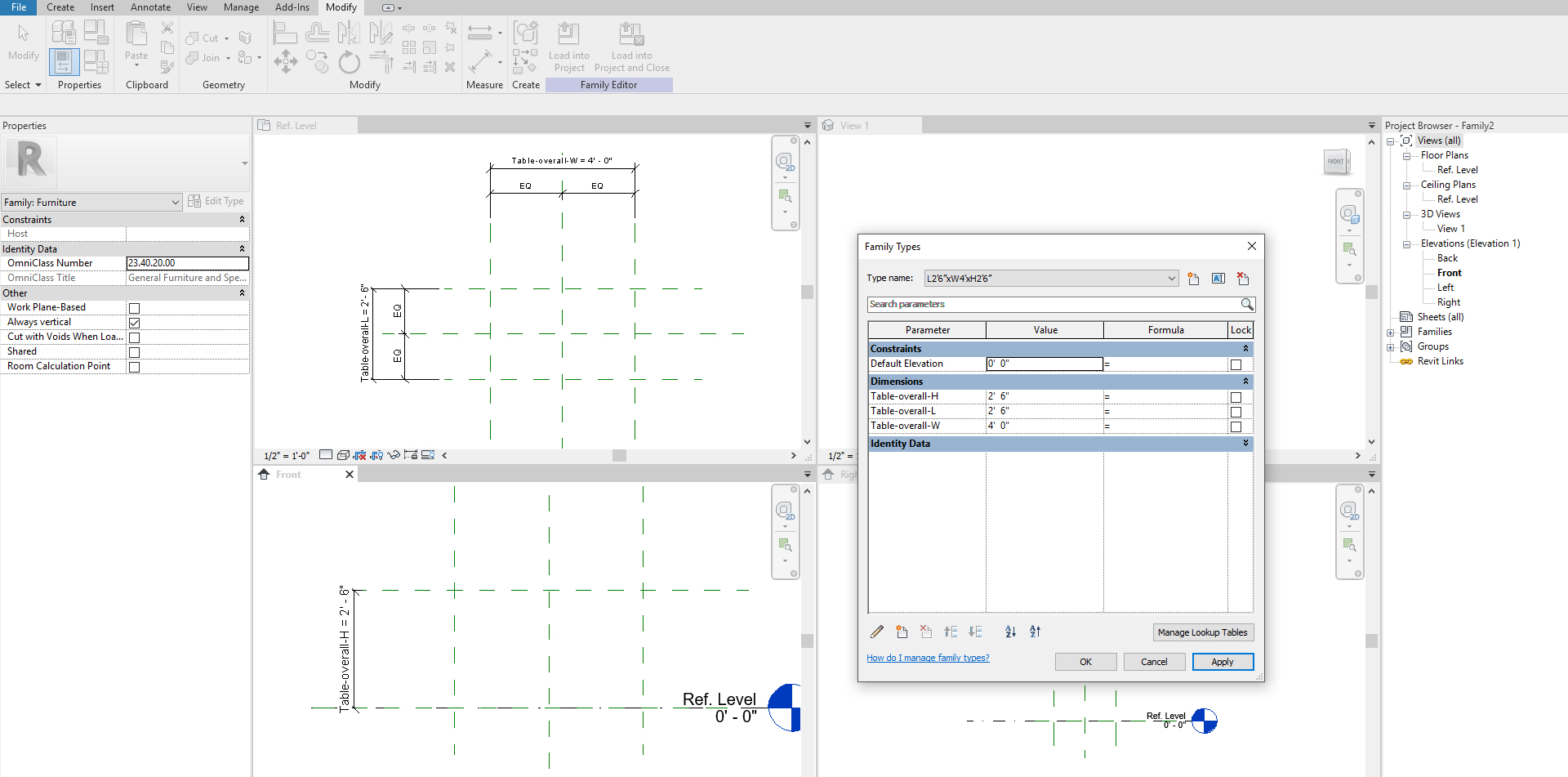
- [STEP 3] Create [Reference Planes] [RP] with [Dimensions] [DI] for overall table width, length, and height.
- [STEP 4] Define parameter.
- Table-overall-W
- Table-overall-L
- Table-overall-H
- [STEP 5] Open [Family type] window > Click [New] > Name [L4’xW2’6”xH2’6”] >Edit the value accordingly.
- [STEP 6] Add detailed reference planes and define parameters.
- If the dimension(s) need a fixed dimension like table thickness, create a reference plane and create dimension and click the lock icon to make it unchangeable. You do not need to define a parameter.
- If the dimension(s) need an adjustable dimension like table-length and width, create a reference plane and create dimension and define a parameter by adding Name.
- Once you click [Instance Parameter], the parameter can be adjusted by dragging and dropping off an arrow.
- Adjust view scale if needed.
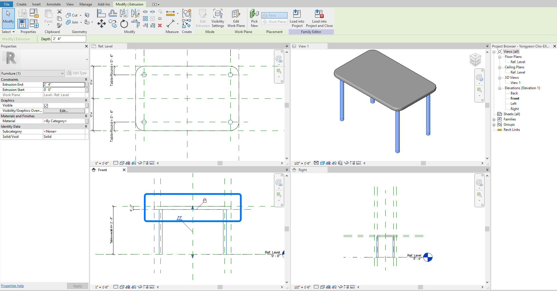
- [STEP 7] Click [Extrusion] > Draw the tabletop by using [Rectangle] align with the guidelines > And make all side locked > Adjust the tabletop and tabletop thickness on the Front view. Do not forget to make it locked.
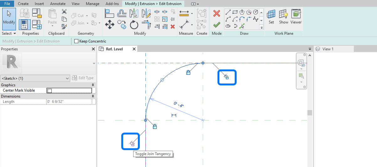
- [STEP 8] Click [Edit Extrusion] > Draw an [Arc] for table round > make [trim] to clean the lines > check [Toggle Joint Tangency] to lock the point.
Repeat this process to all four corners > Click [Green checkmark] to finish.
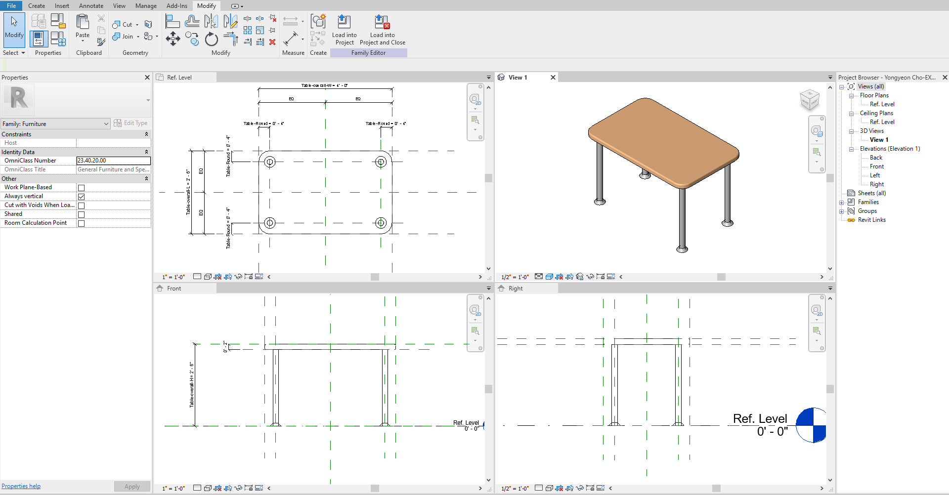
- [STEP 9] Select the tabletop > Click [Associate Family Parameter] by [Material] > Add [New] > Name [Table-Top] > Click [OK] and [OK] to finish.
- [STEP 10] Create a void corner edge by clicking [Sweep] – Click [Create] tab > Click [Void Forms] > Select [Void Sweep] > Draw or Pick Path (the path should be enclosed) > Click Green checkmark to finish drawing path > Click [Modify Sweep] tab > Click [Edit Profile] > Draw an enclosed profile to subtract the form on the reference plan > Click Green checkmark to finish drawing profile > Click Green checkmark again to finish the Sweep tool.
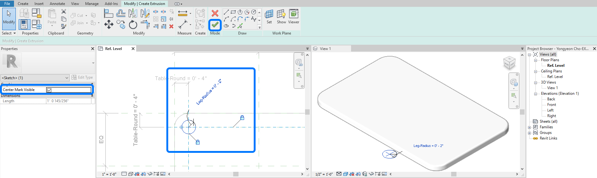
- [STEP 11] Create four cylinders for legs by clicking [Extrusion] > Click [Circle] > Click the center point of a leg > click a point by 2” > click the circle > check [Center Mark visible] > Use align tool to lock the position > Create dimension > Define the parameter [Leg-Radius] > Copy the circle to others and align with the guides > make the dimension for the circle > define the parameter to [Leg-Radius] > Click [Green checkmark] to finish.
- [STEP 12] Adjust the leg height to attach to the bottom of the tabletop > lock the position.
- [STEP 13] Select the table legs > Click [Associate Family Parameter] by [Material] > Add [New] > Name [Table-Legs] > Click [OK] and [OK] to finish.
- [STEP 14] Use [SWEEP] for adding leg details. You must create the details individually with [Pick 3D Edges]. The copy command will not work.
- [STEP 15] Add two materials and apply to the tabletop and the table legs.
 References
Autodesk Help. (May 17, 2015). Create family parameters. Retrieved December 23, 2021, from https://knowledge.autodesk.com/support/revit/learn-explore/caas/CloudHelp/cloudhelp/2015/ENU/Revit-Customize/files/GUID-921F7A15-D191-4F75-8243-4989C482E253-htm.html
Autodesk Help. (July 22, 2021). About parameters. Retrieved December 23, 2021, from https://knowledge.autodesk.com/support/revit/learn-explore/caas/CloudHelp/cloudhelp/2020/ENU/Revit-Model/files/GUID-AEBA08ED-BDF1-4E59-825A-BF9E4A871CF5-htm.html
